Ruckus Cloud RADIUS Configuration
Ruckus Cloud provides multiple authentication methods for Wi-Fi access including external AAA or RADIUS servers to support WPA2 enterprise security. Note that Enterprise AAA flows are very different from guest external captive portal or WISPr flows.
Components of an Enterprise AAA System
-
Supplicant: A client device requiring Wi-Fi access
-
Authenticator: Network device that passes authentication messages between the supplicant and the server for authentication and control access to the network
-
Authentication Server: AAA-compliant server
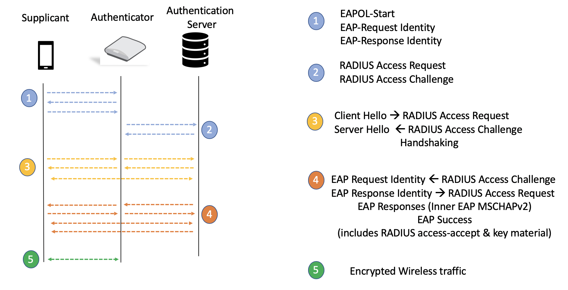
In the Ruckus Cloud Wi-Fi network for the Enterprise AAA profile, the cloud controller operates in non-proxy mode; that is, the access point (AP) is the authenticator and all traffic passes only through the AP and no control traffic reaches the cloud. All WPA2-Enterprise WLANs are site-survivable in the rare event that the connection to the cloud is lost or customers move beyond their license terms. The configuration resides on the AP, and authentication and authorization services continue to function for existing and new clients.
The following figures show a live traffic capture of packets between the supplicant and the authenticator over the air, and between the authentication server and the server on the wire.
Supplicant: admins - MacBook-Pro-6. local
Authenticator: RuckusWi_6a:c2:3c (10.3.6.8)
Authentication Server: 10.3.7.151


The Enterprise AAA network can be enabled in multiple venues. Wireless devices act as supplicants, APs act as the authenticator, and the Enterprise AAA server is the authentication server. Because an Enterprise AAA network can span multiple venues, note the IP address range of APs from all the venues where this network will be broadcast.
In a simple single-venue deployment, from the Ruckus Cloud Wi-Fi UI, navigate to . From the AP IP Address column, you can note the IP address range of the APs. Translate the range into CIDR notation.

Most cloud deployments are distributed across multiple sites. In this scenario, it is simpler to start from the APs tab and note the AP IP address range.
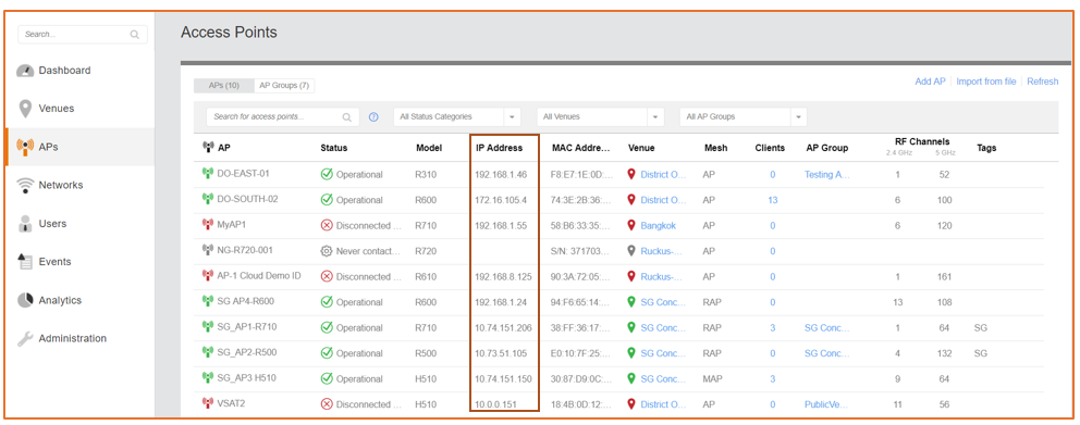
In the case of a mesh network, note that Root Access Points (RAPs) act as authenticators on behalf of Mesh Access Points (MAPs). It is a best practice to include MAP IP addresses in the range, because in failover cases, an Ethernet-Linked Mesh Access Point (eMAP) with a network connection could become a RAP and assume the function of an authenticator.
Once the APs are up and running in the designated venue, begin the configuration on the authentication server for the authenticator and RADIUS clients. The following example covers the steps required for configuration in a Windows NPS server.
Windows NPS Server Configuration
-
Add the AP IP address range in CIDR notation as RADIUS clients.
Figure 83 RADIUS Clients
-
Right-click RADIUS Clients in the left panel and select New. Add the IP address for the AP, verify it, and create a shared secret.
-
A successful verification indicates the AP can reach the server over the network. The system must be configured with the proper DNS entries to resolve the AP IP addresses correctly.
-
Create a shared secret template which can be applied to all the RADIUS clients (APs) that are added so that the secret is the same for all APs on that particular network.
Figure 84 New RADIUS Client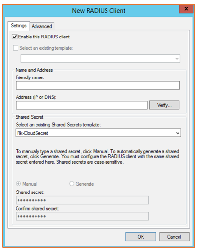
-
-
Create network policies that will be enforced on the supplicants when joining this network.
Figure 85 Cloud Wi-Fi Connection Properties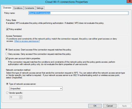
-
In the Conditions tab, add user and computer groups to be allowed for access, network access protection rules, connection properties, and so on.
Figure 86 Conditions for the Connection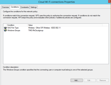
-
In the Constraints tab, define authentication methods and any other constraints to be imposed for the connection.
Figure 87 Constraints for the Connection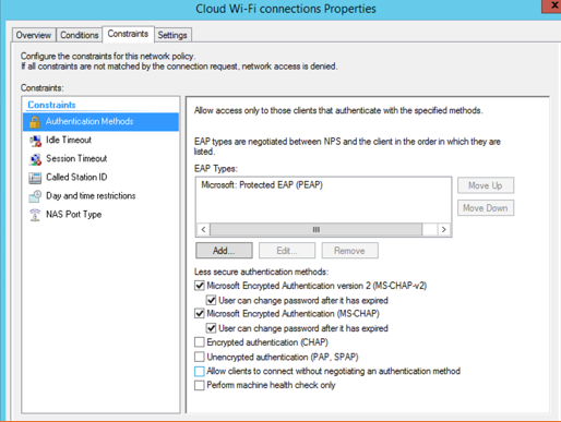
-
In the Settings tab, affix additional RADIUS attributes to RADIUS clients, which will be enforced on the supplicants.
Figure 88 Additional Settings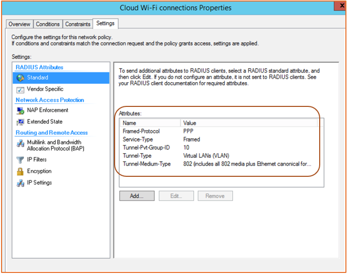
RADIUS Attribute Configuration
Multiple RADIUS attributes can be added to the Wi-Fi connection authentication from the server. These attributes are enforced on RADIUS clients which in turn are enforced on the supplicants in the network.
-
Dynamic VLANs: Allow supplicant devices to be moved into a different VLAN than the one configured in the WLAN controller (the cloud in this case).
The Tunnel-Pvt-Group-ID attribute defines the VLAN group in which the supplicant must be placed.
The Tunnel-Type attribute indicates VLAN versus different VPN tunnels.
The Tunnel-Medium-Type attribute defines the 802-media including the wired (Ethernet) type.
Figure 89 RADIUS Attributes
-
Rate Limiting: Uplink and downlink rate limits per supplicant can be enforced by way of Vendor-Specific Attributes (VSAs) configured from RADIUS.
Add custom VSAs by following the screen instructions. Click Add to continue to the next screen.
Figure 90 Adding Vendor-Specific Attributes
Select a Vendor-Specific RADIUS Standard and click Add.
-
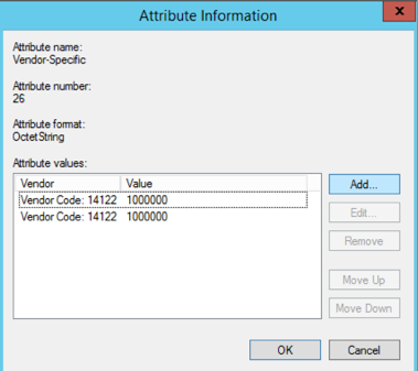
Add rate limiting as a VSA with details such as vendor code, attribute number, and value.
WISPr vendor-specific attributes (Vendor ID = 14122)
(7) WISPr Bandwidth-Max-Up: Maximum transmit rate (bits/second)
(8) WISPr Bandwidth-Max-Down: Maximum receive rate (bits/second)
Figure 91 Adding Vendor-Specific Information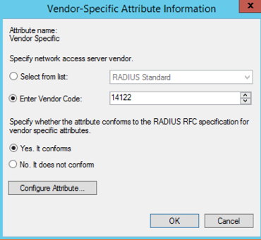 Figure 92 Configuring Vendor-Specific Attribute
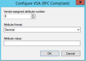 Figure 93 Configured VSA with Values
Wi-Fi Captures of RADIUS Attributes
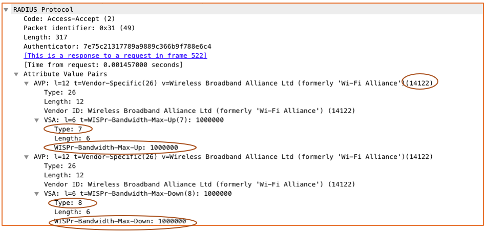
The following figures show a live traffic capture of packets between the authentication server and the authenticator.
Each of the configured attributes has been highlighted for reference.

RADIUS Attribute Uplink and Downlink Rate Limits
Ruckus Vendor ID: 14122
Uplink Attribute ID: 7
Downlink Attribute ID: 8
Ruckus Cloud Configuration
-
Create a WLAN of the Enterprise AAA (802.1X) type.
Figure 96 Creating a Wi-Fi Network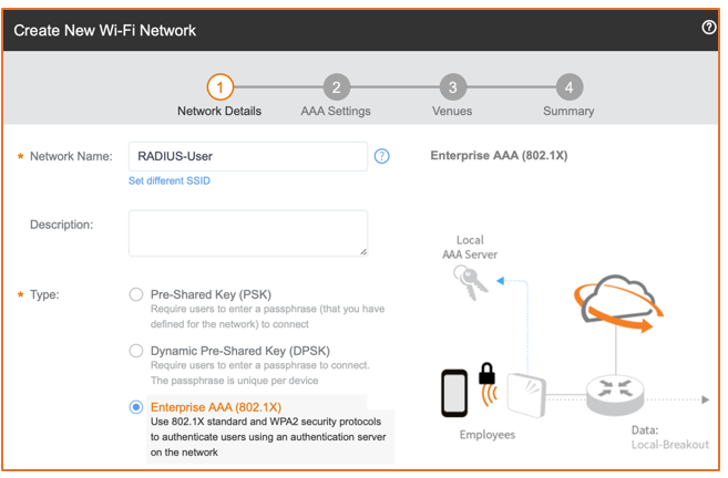
-
Add the server details, including the shared secret that was created.
Figure 97 AAA Settings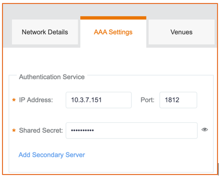
-
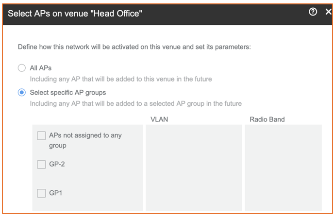
Enable the WLAN in the venue and select specific AP groups or radio bands.
Figure 98 Venues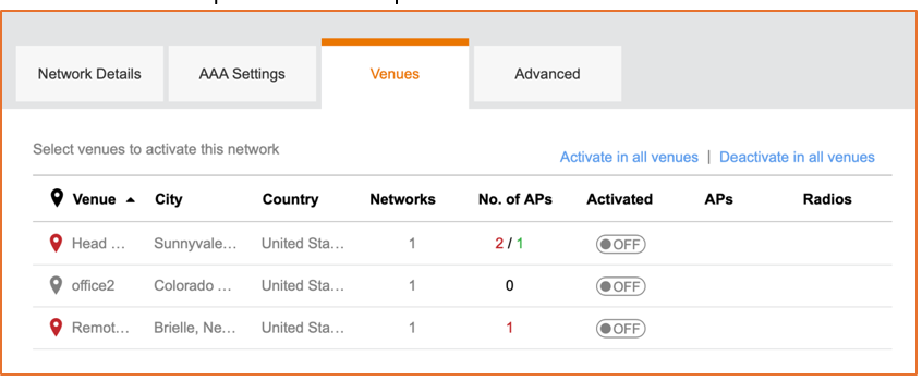 Figure 99 Selecting APs on a Venue
-
Under Advanced Network Setting, enable or disable dynamic VLAN override as necessary (depending on the configuration of RADIUS attributes in the server).
Figure 100 VLAN ID Setting
Selecting the Enable dynamic VLAN check box allows RADIUS to override the default network-configured VLAN and forces the supplicant to the VLAN defined by RADIUS. The dynamic VLAN ID refers to Tunnel-Pvt-Group-ID configured as RADIUS attributes. The attribute is shared in the final Access-Accept packet.
If the Enable dynamic VLAN check box is unselected, the supplicant stays on the network-configured VLAN.
-
There is also an option to add a separate accounting server with primary and secondary options. Add secondary servers for failover scenarios with both authentication and accounting servers.
Figure 101 Adding an Accounting Server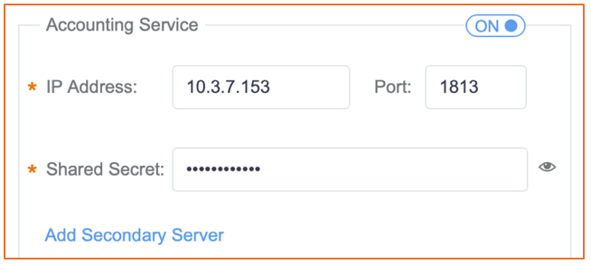
Depending on the network requirements on resiliency, failover options should be configured to ensure seamless operations with security in the network.
Troubleshooting
-
Check that the shared secret is the same on the server and the authenticator.
-
Ensure ports are open for communication between the authenticator and the server.
-
Verify DNS resolution is functional to enable communication between the authenticator and the authentication server.
-
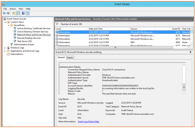
If any issues arise with the authentication itself, use the NPS Event Viewer on the server to view logged error details. (From the Windows Start menu, search for Event Viewer. In the Event Viewer, select Network Policy and Access Servers.)
Figure 102 NPS Event Viewer