Configuring Advanced Network Settings
Advanced network settings include additional options for configuring the network.
After selecting other network options, this is an optional section before the network is actually created. Not all options appear for all types of networks. Exceptions are highlighted. Configure the following advanced network settings:
- From the navigation pane, click
Networks and select a network that you want to edit.
The network Overview page appears.
- In the upper-right corner of the page, click
Manage and then click
Edit Network.The Edit Network dialog is displayed.
- Select the
Advanced tab.
The Advance tab is displayed.
Advance Network Settings 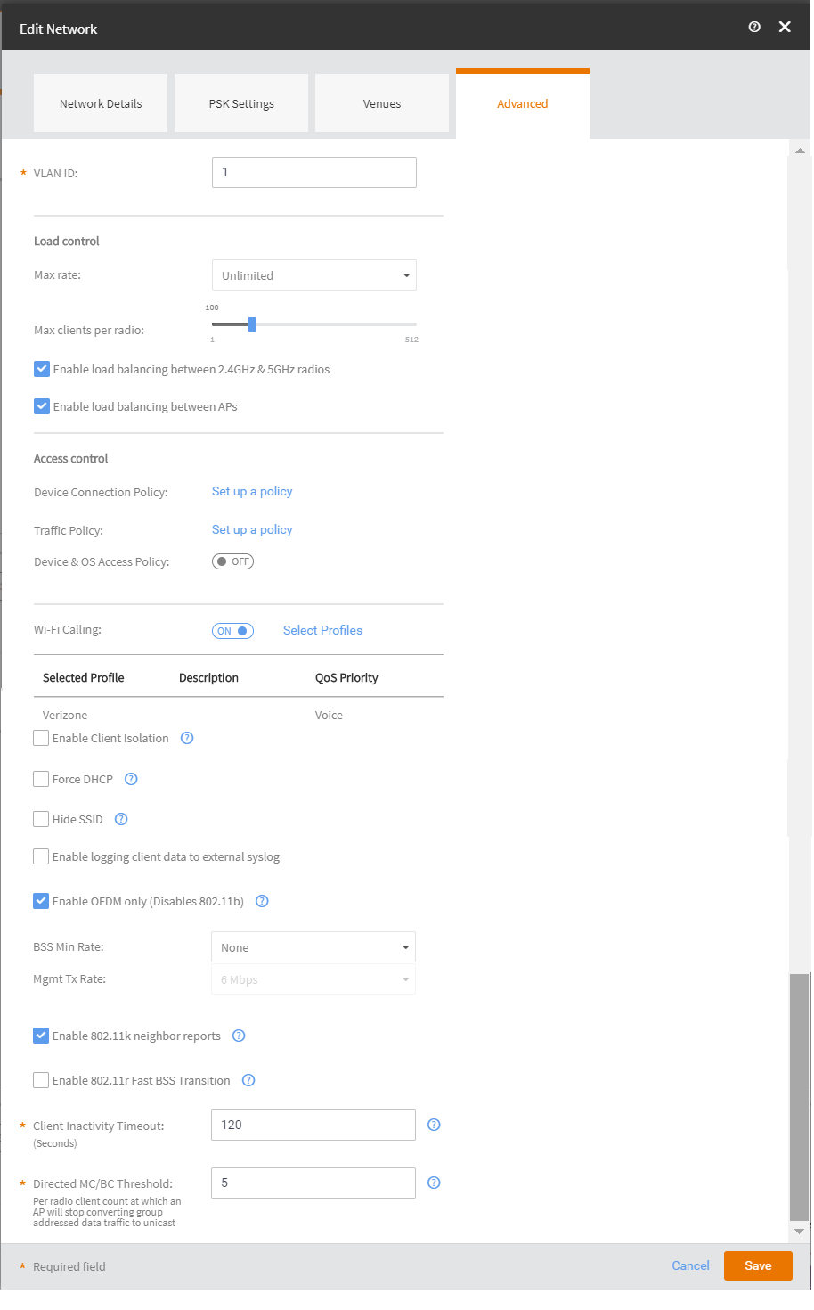
- (Optiona) Toggle the VLAN Pooling to turn it ON . By default, it is set to OFF.
- In VLAN ID: Type the VLAN ID number (default is 1) that you want to assign to this network. The valid range is from 0 to 4096.
- (Optiona) Toggle the Proxy ARP to turn it ON. By default, it is set to OFF.
- In
Max. Number of Devices: (Only for Captive Portal Host Approval and Self Sign In networks) Select the maximum number of devices that can connect to the network.
The drop-down list allows up to 10 devices.
- In
User Connection Settings (Default): (Only for Captive Portal networks except Click-Through)
- Allow the user to stay connected for: Select Minutes or Hours from the drop-down arrow box and then use the up/down arrows to select the number of minutes or hours of connection time after which the client is disconnected.
- Do not redirect to the portal when reconnecting within: You can set the grace period which sets the number of minutes during which previously authenticated clients that disconnect from the network can rejoin the network without going through the authentication process again. The default grace period is 60 minutes, but this time cannot be longer than the allowed user connection period.
- In
User Connection Settings (Time Limited): (Only for Captive Portal Click-Through networks) If you have clicked the
Change to Time limited connection option.
- Allow users to connect for: Enter an aggregated time period after which the user is disconnected. The default is 24 hours.
- After that time, don't allow to reconnect for: Sets a lock-out time during which users are not allowed to sign-in again. The default is 2 hours.
- In the
Load Control section:
- Max rate: There are three options:
- Unlimited—no limits on bandwidth allocation.
- Per AP—The max bandwidth allocation limit of all connections to that specific network on the AP. If selected, two other options appear, Upload Limit and Download Limit. If either (or both) boxes are checked, a sliding scale appears and you can drag your cursor along the line to choose the Mbps limits.
- Per Client—The max bandwidth allocated for a device connected to this network. If selected, two other options appear, Upload Limit and Download Limit. If either (or both) boxes are checked, a sliding scale appears against each option and you can drag your cursor along the line to choose the Mbps limits.
- Max clients per radio: Limit the number of clients that can associate with this network per AP radio (default is 100).
- Enable load balancing between 2.4GHz & 5GHz radios: Select this check box to enable load balancing between the 2.4GHz and 5GHz radios. Load balancing helps improve network performance by helping to spread the client load between the two radios on the AP.
- Enable load balancing between APs: Select this check box to spread the client load between nearby access points, so that one AP does not get overloaded while another sits idle.
- Max rate: There are three options:
- Navigate to the
Access Control section.
- Click
Set up a Policy corresponding to
Device Connection Policy.
The Device Connection Policy dialog box is displayed.By default, the Allow Connections only from MAC addresses listed below option (green) is enabled. You can choose to change this to Block Connections from MAC addresses listed below by clicking the option (red) provided.
- Click Add to add a MAC address. The Add MAC address dialog box is displayed.
- Enter the MAC address and click Add.
- Click Clear list to clear the MAC address list.
- Click
OK to return to the
Edit Network screen.
Note: As an admin user, you can assign a single policy of each type to the network as the default policy or as part of the Network and Venue activation. This action overrides the default network policy.
- Configure a user traffic policy by clicking the Set up a Policy link. The Traffic Policy dialog box is displayed.
By default, the Allow Traffic option (green) is enabled. You can choose to change this to Block Traffic by clicking the option (red) provided. - Click
Set up a Policy corresponding to
Device Connection Policy.
- To create a new traffic rule, click the
Add Rule link. The
Add Traffic Access Rule dialog box is displayed. You can create rules only for up-stream traffic.
Note: L3/L4 traffic policy rules will not be applied to traffic between clients attached to the same WLAN on the same AP.
- Enter a description for the rule in the text field provided.
- You can create a rule to allow or block up-stream traffic by clicking and selecting the Allow Traffic or Block Traffic option, respectively.
- Select the protocol which you wish to use for the new traffic rule, from the
Protocol drop down list. Following are the list of protocols available for use.
- TCP: Transmission Control Protocol
- UDP: User Datagram Protocol
- UDPLITE: Lightweight User Datagram Protocol, which is a connectionless protocol that allows even a damaged data payload to be delivered rather than being discarded.
- ICMP (ICMPV4): Internet Control Message Protocol, which is an error-reporting protocol used by network devices to generate error messages to the source IP address, when issues in the network prevent delivery of IP packets.
- IGMP: Internet Group Management Protocol, which is a communications protocol used by hosts on IPv4 networks to establish multicast group memberships.
- ESP: Encapsulating Security Payload is a protocol which provides the authentication, integrity, and confidentially of network packets in IPv4 and IPv6 networks.
- AH: Authentication Header protocol, which is used to authenticate SNMP.
- SCTP: Stream Control Transmission Protocol is a communications protocol which operates at the transport layer.
- Specify the source address in the Source field. You can either specify a range (a network address and a Subnet Mask, in the field provided) or you an specify a source IP address in the field provided. Also, specify a port number or a range of ports (for example, 22-34) for the source, in the field provided.
- Specify the destination address in the
Destination field. You can either specify a range (a network address and a Subnet Mask, in the field provided) or you an specify a source IP address in the field provided. Also, specify a port number or a range of ports (e.g: 22-34) for the destination, in the field provided.
Note: If you choose the ICMP protocol in the previous step, you do not need to specify ports for the source and the destination. Hence, the option to select ports will not be presented to you.
- Click
Save. The rule which you created appears in the
Traffic Control Policy dialog box.
Note: The rule which you initially create appears in a row with priority set a "1", by default. When you create a second rule, it appears in the row with priority "1" and the previous rule which you created appears as second in the row, with priority "2". When you have multiple rules created, you can use the "up" and "down" arrows available at the end of each row, to shift respective rows up or down in the order, to set the desired priority.
The edit and delete links available at the end of each row allow you to edit and delete respective rules. Each time you click the edit button, the Add Traffic Access Rule dialog box is displayed. where you can edit any of the rule properties.
- Click
OK in the
Traffic Policy dialog box, once you have all the required rules added.
You are navigated back to the Advanced Network Settings dialog box, where are can click the Traffic Policy toggle button to "ON" or "OFF", activating or de-activating the traffic policy which you created, respectively. The Edit option allows you to navigate to the Traffic Control Policy dialog box, where you can edit the policy which you created. The Clear button allows you to delete the traffic policy.
- To add a device and OS access policy, toggle the
Device & OS Access Policy option to
ON.
- Choose a device and OS access policy from the Select policy drop down.
- Click Add to add a device and OS access policy. The Add Device & OS Access Policy dialog box appears.
- Complete the following:
- Policy Name: Enter the name of the policy.
- Description: Enter description for the policy.
- Default Access: Select either Allow or Block.
- Click
Add Rule and then complete the following:
- Rule Name: Enter the name of the rule.
- Action: Select either Allow Devices or Block Devices.
- Device Type: Select a device type from the list of devices.
- OS Vendor: Select the OS vendor for the devices.
- Rate Limit: Configure the late limit using the sliders: From client and To client.
- VLAN: Enter the VLAN ID.
- Click ADD to add the rule to the device and OS access policy for the network .
- Toggle the DNS Proxy option to ON to add DNS proxy. In the DNS Proxy page, click Add Rule to access the Add DNS Proxy Rule page. Enter a domain name and IP address in the appropriate fields and click Add.
- Toggle the
Wi-Fi Calling option to
ON and click
Select Profiles to select a Wi-Fi calling profile.
By default, the Wi-Fi Calling is set to OFF
- In Enable Client Isolation: Select this check box to prevent clients on the same network from communicating with each other.
- Toggle the Automatic support for VRRP/HSRP switch to ON to enable this feature.
- Toggle the Anti-spoofing switch to ON to configure the ARP request rate limit and DHCP request rate limit.
- In
Force DHCP: Select this check box to force clients to obtain a valid IP address from a DHCP server. This prevents clients configured with a static IP address from connecting to the network.
If a client performs Layer 3 roaming between different subnets, in some cases the client sticks to the former IP address. This mechanism optimizes the roaming experience by forcing clients to request a new IP address.
- In Hide SSID: Select this check box if you do not want the ID of this network advertised at any time. This will not affect performance or force the network user to perform any unnecessary tasks.
- In Enable OFDM only (Disables 802.11b): Enabling this option disables CCK rates of 1, 2, 5.5, and 11 Mbps, so no 802.11b-only clients can connect. Beacons and probe responses will be transmitted at 6 Mbps, and data frames at 6, 9, 18, 24, 36, 48, and 54 Mbps. Enforcing higher minimum data rates increases overall network throughput capacity, but reduces the distance at which clients are able to remain connected.
- In Enable logging client data to external syslog: Select this check box to allow client data to be logged in all venues that have the external syslog server enabled. The box is unchecked by default. Refer to the Configuring the Syslog Server for a Venue page for details about configuring the external syslog server for a venue.
- In BSS Min Rate: Use this option to configure the minimum transmission rate supported by the network. If OFDM Only is enabled, the only valid options are 12 Mbps and 24 Mbps, with Mgmt Tx frames fixed at 6 Mbps. This option can also be used to prevent 11b clients from connecting, and to allow greater client density with higher data rates.
- In Mgt Tx Rate: This option is only available if both OFDM Only and BSS Min Rate are disabled. (Otherwise, the Mgmt Tx Rate is defined by those settings.) Use this setting to configure the rate at which management frames are sent. The default is 6 Mbps.
- Enable 802.11k neighbor reports: Enhances roaming by providing a list of neighbor APs to the client device.
- Enable 802.11r Fast BSS Transition: 802.11r Fast BSS Transition fast roaming protocol.
- Client Inactivity Timeout: Client will be disconnected from the network if it is inactive for more than the time interval specified. The timeout period can range from 60 through 1000 seconds.
- Airtime Decongestion: Toggle the switch to ON to activate the airtme decongestion feature.
- RSSI Threshold: Toggle the switch to ON and then cofigure the threshold value.
- Transient Client Management: Toggle the switch to ON and the configure parameters for Join Wait Time, Join Expire Time, and Join Wait Threshold.
- Optimized Connectivity Experience (OCE): Toggle the switch to ON and then and confiture parameters for Broadcast Probe Response Delay and RSSI-Based Association Rejection Threshold.
- Click Reset to Defaults button in the lower left side of the screen to reset all the advanced settings back to their defaults.
- Click Save to save your settings.