Creating an LTE Network
The CBRS Alliance has provided detailed guidelines for computing a unique E-UTRAN Cell Global Identifier (ECGI) per CBSD to all CBSD (LTE AP) vendors.
You are presented with following two options:
- WiFi Network
- LTE Network
- Click
LTE Network.
The Create New LTE Network page appears to allow you to complete the settings on the Network Details tab.
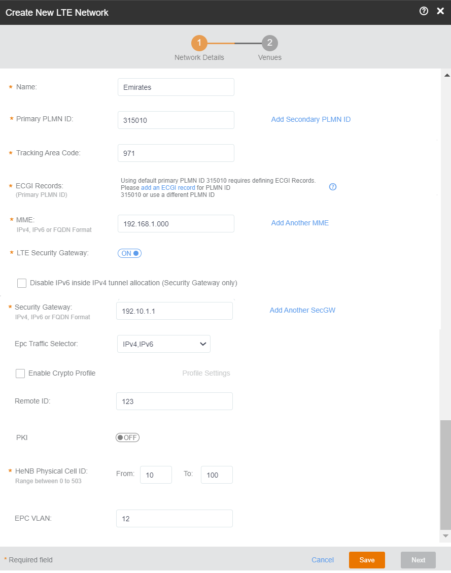
- In the Name filed, enter a name that you want to assign to the LTE network.
- By default, the shared CBRS-A PLMN ID, 315010 is populated in the PLMN ID field. The
PLMN ID can be overwritten with any other valid PLMNID, if desired.
A PLMN is identified by the Mobile Country Code (MCC) and the Mobile Network Code (MNC). Each operator that provides mobile services has its own unique PLMN ID.Note:
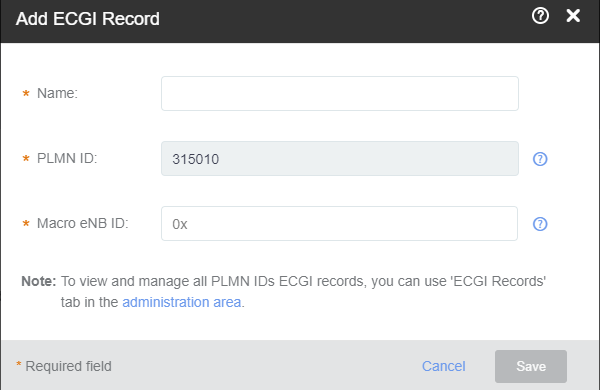
According to the CBRS-A guidelines, to create a new CBRS Network using the shared PLMN ID (315010), all operators must purchase "Macro eNB ID" from the Alliance. For more information, refer to Adding ECGI Records.
Configure the Macro eNB IDs and PLMN ID to create globally unique ECGI records/ range that can be assigned to Cells coming up within the network.
If the PLMN ID used is not the shared CBRS PLMN ID, operators have two options as elaborated below. For more information, visit: http://imsiadmin.com and http://atis.org/ioc.
- Click
Add Secondary PLMN ID to add a secondary PLMN ID. Optionally, click
Add Another PLMN ID to add an another PLMN ID.
You can add up to six secondary PLMN IDs.
- Enter the tracking area code in theTracking Area Code field.
- In the
ECGI Records drop-down, select a desired record and click
OK.
The number of available ECGI records are displayed in the Available ECGI field.
- (Optional) Click
+Add ECGI Record to add a new ECGI record.
- In the
MME section, enter the address of the Mobility Management Entity (MME).
The address can be an IPv4, IPv6, or a Fully Qualified Domain Name (FDQN). The MME is the key control-node for the LTE network access. It works with the LTE AP (eNodeB) and Serving Gateway (SGW) within the Evolved Packet Core (EPC) and is responsible for initiating paging and authentication of the mobile device. You can configure multiple MME control points.
To add more than one MME IP control points, click Add another MME link and enter the MME IP address or FQDN (domain name) in the additional field that appears. Click the Remove MME link that appears adjacent to each MME added, to remove an MME IP.
- In the
LTE Security Gateway section, click the toggle button to enable or disable the Security Gateway (SecGW).
The SecGW protects network elements and secure communication links across the LTE network by providing traffic encryption between LTE APs and EPC. It authenticates network elements to avoid a rogue LTE AP connecting to the network. It manages and controls traffic delivered to avoid network downtime.Note: Confirm the SecGW availability and connection details with your EPC vendor.
Contact Ruckus Support to upload root certificates for your SecGW using this menu.
- Check the Disable IPv6 inside IPv4
tunnel allocation (security gateway only) check box if you want
to disable IPv6 inside IPv4 tunnel allocation. By default, this option is
enabled.
You can configure the security gateway in the IPV6, IPV4, or FQDN format and enable, disable the SECGWIPV6INV4 independently.
- Complete the following Security
Gateway settings which are presented to you when you enable the LTE Security
Gateway.
- In the Security Gateway section, enter the IPV4 address, IPv6, or FQDN of the SceGW, in the field provided. You can add multiple SceGW by clicking Add Another SecGW link.
- In the PKI section, click the toggle button to enable the PKI. You are now provided with fields to enter CMP server URL and the CA.
- In the optional CPM server URL section, select the check box and enter the URL to connect to the CPM Server using the HTTPS protocol. When a CPM server boots for the first time, it will automatically create a self-signed SSL certificate.
- In the optional Certificate
Authority section, select the check box and enter the
repository URL, user name, password and the URL Hash in the respective text
fields provided.
- (mandatory) Repository URL: Enter the URL of the Web server that hosts the CA.
- (optional) User Name: The user name to access the Web Server.
- (optional) Password: The password to access the Web Server.
- (mandatory) URL Hash: Enter the 64 hex character certificate hash.
- In the Tracking Area Code section, enter the unique Tracking Area Code (TAC) assigned to the LTE tracking area (TA), which helps in identifying the UE location. When an LTE device (UE) is in active state, its location is known by the LTE network at the LTE AP level. However, when the UE is in idle state, its location is known by the LTE network at TA level. An operator defines a group of neighboring LTE APs as a TA. Each TA has a Tracking Area Identifier (TAI). A TAI consists of a PLMN ID and a TAC. A PLMN ID is a combination of a Mobile Country Code (MCC) and a Mobile Network Code (MNC), which is the unique code assigned to each operator
- In the Physical Cell ID section, enter the physical layer cell ID (PCI) range. The physical cell ID identifies a network cell in the physical layer. This property is limited to 504 values ranging from 0 through 503; and therefore, it needs to be reused in the network. SON will allocate PCIs with optimal separation between neighbor Cells; however, ensure that enough range is provided. The physical cell ID of each AP should differ from physical cell ID of its neighbors. The tenant must ensure that enough range is provided for the correct distribution.
- EPC VLAN: This is an optional field. You can leave it blank unless specific VLAN requirements are provided by your IT.
- Check the Enable Crypto Profile check box, click Profile Settings and complete the profile setting, and then click OK.
-
From the Epc Traffic Selector drop-down, select one of
these:
- IPv4
- IPv6
- IPv4, IPv6
- (Optional) Enter the remote ID in the Remote ID field.
- Toggle the PKI button to ON or OFF.Complete the following:
- CMP server URL
- CMP v2 SecGW
- Certificate Authority
Configure the Repository URL. Enter the user name and passwordEnter the Certificate Hash. - Configure the HeNB Physical Cell ID. The valid range for physical cell ID is from 0 through 503
- Enter the VLAD ID in the EPC VLAN field.
- Click the
Next button to navigate to the
Venues tab. The
Venues tab allows you to select venues in which you want to activate the network.
Venues are displayed in the tabular format as displayed in following figure. Each row displays venue details such as City, Country and the number of Networks, APs, and clients. For the venues which have networks and APs configured, the flag against them appears in green, and for the ones without any configuration, the flags are grayed out. Pause the mouse pointer over the green flag prompts you that the venue is All good. Pause the mouse pointer over the grayed out flag prompts you that the venue is In setup phase.Note: You can skip this step and choose to select venues after the LTE network is created.
Selecting Venues 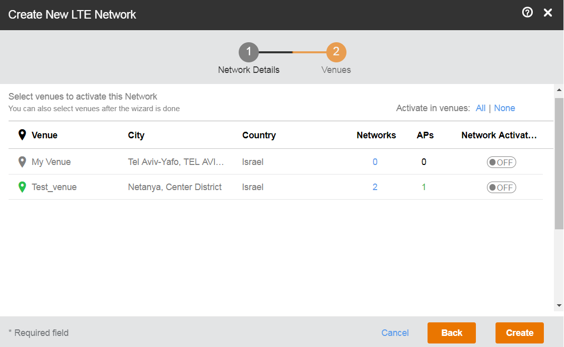
- Click the toggle button available in the
Network Activation column to activate the desired venue.
Note: If the venue already has an activated LTE network, you are prompted with a dialog box, stating that the venue already has an activated LTE network. If you want to deactivate the existing one and activate the new LTE which you are creating, click Activate Network to continue.
You can choose to activate your LTE network in all the venues by clicking the All button available on top of the Network Activation column. If any of the venues has an already activated LTE network, you are prompted with a dialog box stating that the venues already has an activated LTE network. If you want to deactivate the already active LTE network and activate the one which you are creating, click the Activate Network button to continue. You can choose to not activate your LTE network in any of the venues by clicking the None button on top of the Network Activation column.
- The number of networks configured in any venue is listed under the Networks column. Pause the mouse over the number to display other networks activated in that venue. Click to display the corresponding venue details page where you can change the already existing configuration, before proceeding to create your LTE network.
- The number of APs configured in any venue is listed under the APs column. Pause the mouse over the number to display the configured APs in that venue. Click to display the corresponding AP details page where you can change the already existing configuration, before proceeding to create your LTE network.
- After completing all the required configurations for your LTE network, click the Create button. A dialog box prompts you that your network is being activated. If the process is successful, you are navigated to the Networks page, where your newly created LTE network is listed.