Setting up a Network Using the AI Onboarding Assistant
You can set up an efficient and secure network using the Onboarding Assistant which automates and optimizes complex network onboarding processes and increases efficiency and productivity.
-
On the RUCKUS One web interface,
click the
 icon in the UI header.
The RUCKUS DSE welcome message appears in an interactive pop-up window.
icon in the UI header.
The RUCKUS DSE welcome message appears in an interactive pop-up window.Invoking the RUCKUS DSE 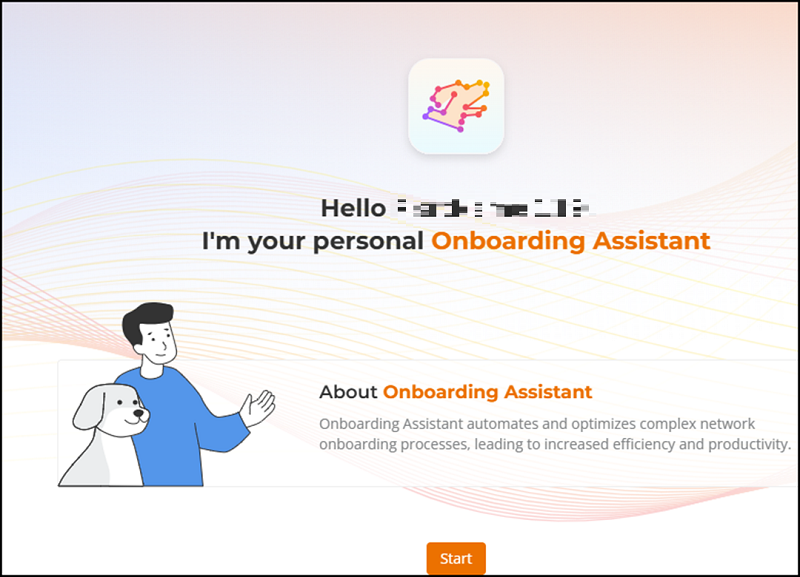
-
Select Help me set up my network.
Invoking the Onboarding Assistant 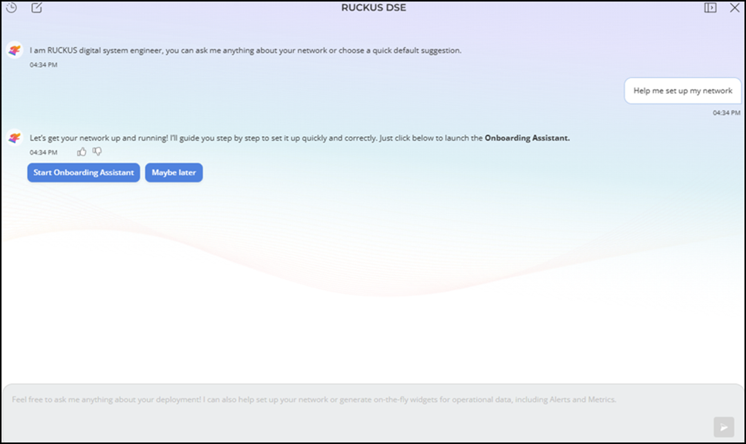 Note: This step-by-step example will proceed with choosing a quick default suggestion, but you can also ask anything about your network in the chatbox.
 -
Select Start Onboarding Assistant.
The Onboarding Assistant page is displayed with venue type options.
Venue Types 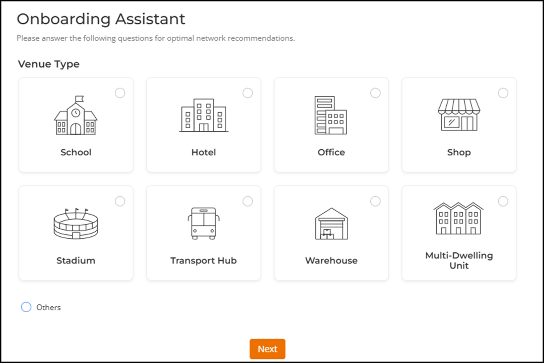
-
Select the venue of choice from
the Venue Type section.
Venue types include:
- School
- Hotel
- Office
- Shop
- Stadium
- Transport Hub
- Warehouse
- Multi-Dwelling Unit
- Others
-
Click Next.
The Venue Details page is displayed.
-
Configure the following fields:
- Venue Name: Enter a name to identify the venue.
- (Optional) Approx. Number of APs: Enter the number of APs required for the deployment.
- (Optional) Approx. Number of Switches: Enter the number of switches required for the deployment.
- (Optional) Tell me more about the deployment: Enter more information about the premises. For example, you can specify the total number of users to support, user roles based on which network access must be provided, total number of floors, server rooms, labs, common areas, outdoor spaces, and so on. You can also specify the network infrastructure to use, including routers, switches, and access points.
-
Click Next.
The Recommended Network Profiles page is displayed providing information on recommended SSID profiles based on inputs entered in the Venue Details page. The number of recommended network profiles varies by venue type. Each suggested network profile includes:
- Network Name: Edit the network name as needed.
- Network Objective: Edit the objective by selecting an option from the drop-down menu. The Network Objective defines the purpose and access level of various network connections within an organization, including Internal (for employees and students), Guest (for visitors), VIP (for high-priority guests), Infrastructure (for devices like VoIP phones and cameras), Personal (for personal devices), and Public (for open use without authentication). This ensures appropriate access and security for each user group and device type.
- Purpose: This information element provides the purpose and reasoning behind each suggested network.
The Add Network Profile link is disabled if the list has more than 5 items.
Recommended Network Profiles Page 
- Choose one or more network profiles for your venue. By default, all recommended network profiles are selected. Click the checkbox next to the Network Name to deselect or reselect profiles.
-
Click Next.
The Recommended Network Configuration page is displayed listing the SSIDs and their recommended configurations based on your selections. The network objective determines the network type that is selected. The Onboarding Assistant applies the objective-type logic as follows:
Network Objective Internal Guest and VIP Infrastructure Personal Public Network Type Enterprise AAA (802.1X) Captive Portal Dynamic Pre-Shared Key (DPSK) Passphrase (PSK or SAE) Open Network Recommended Network Configuration 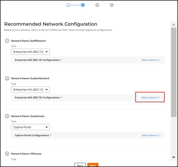 Note: Although the AI Onboarding Assistant preselects the most appropriate network type, you may change the network type for any SSID by selecting a different type from the drop-down list.
 -
For every SSID, click Setup Network to
launch the network configuration wizard. Modify and confirm the network
configuration settings and click Add to save the
configuration and close the wizard. The network configuration is saved and
displayed as Configured
(green text) in the Recommended Network Configuration page.
Recommended Network Configuration - Configured 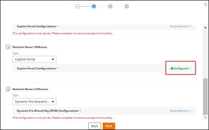 Note: All networks must be in Configured status to proceed to the next step.
 -
Click Next.
The Recommended Switch Configuration page is displayed providing information to set up VLANs for the network. You can continue with the recommendations provided, or choose to ignore them by clicking Skip this step.
The Add VLAN link is disabled if the list has more than 5 items.
Recommended Switch Configuration 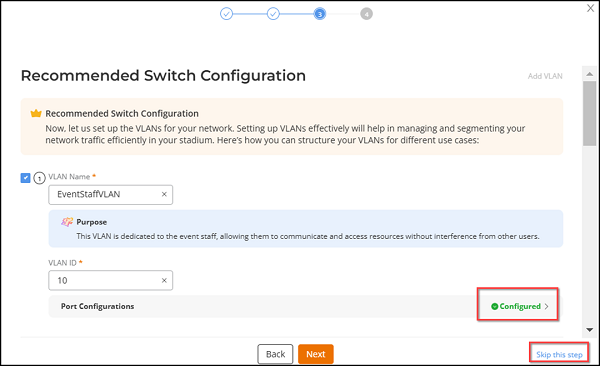
Each suggested VLAN includes:
- VLAN Name: The VLAN Name is provided by the Onboarding Assistant, however, you can edit this name.
- Purpose: This information element provides the purpose and reasoning behind the suggested VLAN.
- VLAN ID: The VLAN ID is already populated by the assistant based on previous inputs, however, you can change the value.
- (Optional) Port
Configuration: Configure ports for the VLAN by following these
steps:
Port Configuration for VLAN 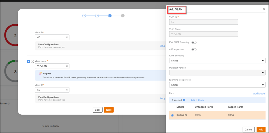
- Click Setup Ports. The Add VLAN sidebar is displayed.
- In the
Add VLAN sidebar, configure the
following:Note: VLAN ID and VLAN Name are disabled and cannot be edited.
- IPv4
DHCP Snooping: This security feature is used on
network switches to prevent unauthorized or rogue DHCP
servers from distributing IP addresses within a
network.Note: If IPv4 DHCP Snooping is enabled, you must select trusted ports. You can set up the trusted ports in the switch console.
- Address Resolution Protocol (ARP) Inspection:
This security feature validates ARP packets to prevent
ARP spoofing attacks, which involve an attacker sending
fake ARP messages to intercept network traffic.Note: If ARP Inspection is enabled, you must select trusted ports. You can set up the trusted ports in the switch console.
- IGMP Snooping: This network switch feature monitors Internet Group Management Protocol (IGMP) traffic to manage and control the delivery of IP multicast packets. Active IGMP snooping involves the switch sending IGMP queries to manage multicast group memberships, while passive IGMP snooping relies on listening to existing IGMP traffic without the switch generating its own queries. Select Active, Passive, or NONE from the drop-down menu. You cannot set the Multicast Version if NONE is selected.
- Multicast Version: This option refers to the version of Internet Group Management Protocol (IGMP) used for optimizing multicast traffic in the network. Version 2 provides basic multicast group management functions, while Version 3 offers advanced features (such as source-specific multicast) and improved security. Select Version 2 or Version 3 from the drop-down menu.
- Spanning tree protocol: This network protocol is used to create a loop-free logical topology for Ethernet networks. Select one of the protocol versions: RSTP, STP, or NONE from the drop-down menu.
- Click Add Model to add the switch family, model, untagged ports, and tagged ports.
- Click
Add.
The VLAN ports are set up, and the status shows as Configured in green text.
- IPv4
DHCP Snooping: This security feature is used on
network switches to prevent unauthorized or rogue DHCP
servers from distributing IP addresses within a
network.
-
Click Next.
The Summary page is displayed consolidating all the network details. You can click Edit to make changes to the configuration settings.
Summary Page 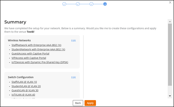
-
Click Apply.
A confirmation message is displayed after the configuration is applied and the new Wi-Fi network is created. Green activity messages appear in quick succession, signifying success of each of the individual configuration activities triggered by the Onboarding Assistant. You can view the configuration-related activity details from Administration > Timeline > Activities or by clicking the
 icon on the top-right corner of the RUCKUS One web interface.
Confirmation Message and Activities Page Updates 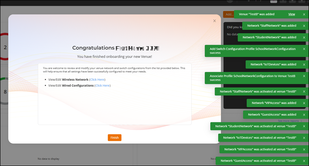
You can review and modify wireless and wired configurations by clicking Click Here.
-
Click Finish.
The new venue is listed in the Venues page.
The new networks are listed in the Wi-Fi > Wi-Fi Networks List page.
The new switch configuration profile is listed in the Wired > Configuration Profiles page.