Creating a Network That Uses a Captive Portal with Active Directory (AD) or LDAP Server
You can create a captive portal network that allows users to join by entering an organization-based username and password, which are authenticated by an associated Active Directory (AD) server or an LDAP (Lightweight Directory Access Protocol) server.
-
On the navigation bar, click
Wi-Fi > Wi-Fi
Networks > Wi-Fi Networks
List.
The Wi-Fi Networks page is displayed.
-
Click Add Wi-Fi
Network. Alternatively, select an existing Captive Portal Wi-Fi
network with Active Directory/LDAP Server setting that you want to copy and
click Clone at the top of the table.
The Create New Network page is displayed.
-
Complete the settings on the
Network Details page.
- Network Name: Enter a name (2 to 32 characters) for a network. By default, this name is also used as the SSID.
- (Optional) Set
different SSID: Click Set different
SSID to configure an SSID different from the network
name. The SSID field is displayed.
- SSID: Enter an SSID name (2–32 characters; up to 32 bytes for UTF‑8 non‑Latin characters).
- (Optional) Description: Enter a description to help you identify the network.
- Network
Type: Choose Captive
Portal.
A structure diagram of a Captive Portal is displayed.
Note: If you used the Clone option, the Network Type is already set to Captive Portal.
-
Click Next.
The Portal Type page is displayed.
-
Click Active Directory/LDAP
Server.
The structure diagram on the right updates to show the Active Directory or LDAP network type.
-
Click Next.
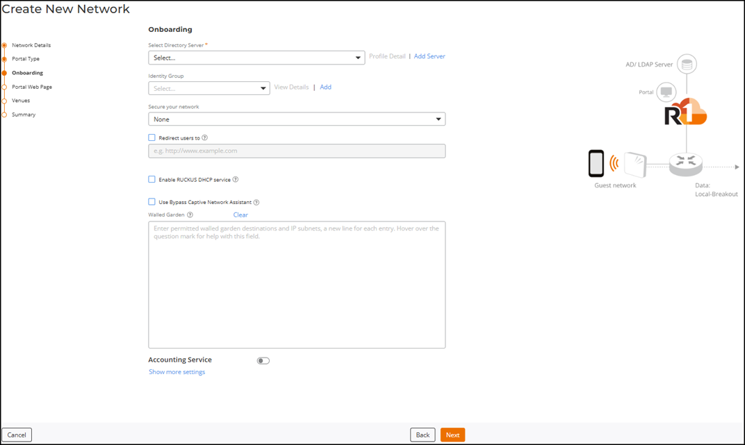
The Onboarding page is displayed.
Active Directory/LDAP Server - Onboarding 
- Select Directory Server: Select an Active Directory or LDAP server profile from the drop-down or click Add Server to create a new Active Directory or LDAP server profile. Refer to Adding and Managing a Directory Server for more information. If you select an existing profile, you can click Profile Detail to easily view the Directory Server Details in a sidebar without leaving the network creation wizard.
-
Identity Group:
Select an identity group from the drop-down or click Add to add an
identity group. Refer to Adding an Identity Group for instructions on how
to add an identity group.
Note: When an identity group is selected, all devices joining the network automatically become an identity within that group, as displayed on the Identity Group page.To view details about the identity group, click View Details. The Identity Group sidebar is displayed.
-
(Optional) Secure your
network: Select a Secure your
network method. The options are:
- None (default): No encryption method is used.
- Pre-Share Key
(PSK): Select Pre-Share Key
(PSK) and select a security protocol for the network.
- Passphrase: Enter a Passphrase (minimum 8 characters) and
select a Security
Protocol. The options are:
- WPA2 (Recommended) (default): Select
WPA2 (Recommended) and enter a
passphrase of at least eight characters in the
Passphrase field.
WPA2 provides strong Wi‑Fi security and is widely supported on devices manufactured after 2006. Select WPA2 unless your deployment requires WPA3. 6 GHz radios are only supported with WPA3.
- WPA3: Select WPA3 and enter a passphrase of at
least eight characters in the SAE
Passphrase field.
WPA3 provides the highest Wi‑Fi security and is supported on most devices manufactured after 2019.
Note: The IEEE 802.11ax (Wi-Fi 6E) and IEEE 802.11be (Wi-Fi 7) APs support only WPA3. The 6 GHz radios support WPA3 only. - WPA2/WPA3 mixed mode: Select
WPA2/WPA3 mixed mode and enter a
passphrase of at least eight characters in the
WPA2 Passphrase and WPA3 SAE Passphrase fields.
WPA2/WPA3 mixed mode lets devices connect using either WPA3, the most secure Wi-Fi standard, or WPA2, which is still widely supported. Most devices made after 2006 support WPA2, and those from 2019 onward typically support WPA3.
Note: Select WPA3 or WPA2/WPA3 mixed mode if you broadcast on 6 GHz.
- WPA2 (Recommended) (default): Select
WPA2 (Recommended) and enter a
passphrase of at least eight characters in the
Passphrase field.
- Passphrase: Enter a Passphrase (minimum 8 characters) and
select a Security
Protocol. The options are:
- OWE
Encryption: Opportunistic Wireless Encryption (OWE)
provides encrypted communications for open Wi-Fi networks without
passwords. Choose this option to allow users to access the network
without entering a password for authentication. If you selected
OWE
Encryption, configure the following field:
- (Optional)
OWE Transition mode: Toggle the OWE
Transition mode switch on to enable a seamless
transition from open, unencrypted WLANs to OWE WLANs without
adversely impacting the end user experience. Note: OWE transition mode allows STAs that do not support OWE authentication to access the network in open authentication mode, while OWE-capable STAs can use OWE authentication mode.
The migration to an enhanced open Wi-Fi network is done gradually, with user devices also upgrading over time. In OWE Transition mode, an AP creates two SSIDs as a pair: SSID1 (broadcast) for open authentication and SSID2 (hidden) for OWE authentication (read-only). Non-OWE devices connect to SSID1, while OWE-capable devices initially connect to SSID1 but are then associated with SSID2 for secure access.
Deleting SSID1 or disabling OWE Transition also deletes SSID2; cloning SSID1 creates two new WLANs. SSID1/SSID2 co‑exist as a pair; a maximum of six WLANs can be created per venue, per AP group.
- (Optional)
OWE Transition mode: Toggle the OWE
Transition mode switch on to enable a seamless
transition from open, unencrypted WLANs to OWE WLANs without
adversely impacting the end user experience.
-
(Optional) Redirect Users
to: Select the Redirect Users to
checkbox and enter a valid URL.
You can redirect users to your company website or another URL after they log in successfully. If the checkbox is not selected, users are sent to the page they originally requested.
- (Optional) Enable RUCKUS DHCP service: Select the Enable RUCKUS DHCP service checkbox to automatically create and assign a new DHCP-Guest Service and DHCP Pool for Guest WLAN-related venues that do not have a specified DHCP Service. Refer to the DHCP Service of each Venue for more information.
- (Optional) Use Bypass Captive Network Assistant: Select the Use Bypass Captive Network Assistant checkbox to enable this option. Enabling this option prevents the controller from using the mini-browser on mobile devices. With CNA bypass enabled, portal login is achieved by opening a standard browser to any unauthenticated HTTP page to get redirected to the login portal.
-
(Optional) Walled
Garden: Enter Walled Garden destinations (URLs or IP addresses)
that users can access before authentication.
A walled garden is a limited environment that allows unauthenticated users to access specific destinations so they can set up an account. After the account is established, the user is allowed out of the walled garden. Unauthenticated users will be allowed to access these destinations (i.e., without redirection to captive portal). Each destination should be entered in a new line. Accepted formats for destinations are:
- IP address (for example, 10.11.12.13)
- IP address range (for example, 10.11.12.13-10.11.12.15)
- CIDR (for example, 10.11.12.13/28)
- IP address and mask (for example, 10.11.12.13 255.255.255.0)
- Website FQDN (for example, www.ruckus.com)
- Website FQDN with a wildcard (for example, *.amazon.com; *.com)
-
Accounting
Service: Toggle the switch on to enable this option and select
the existing RADIUS Server from the drop-down list or complete the following
steps to add a new RADIUS Server.
- Click Add Server and configure a new RADIUS Server. Refer to Adding and Managing a RADIUS Server.
-
Proxy
Service: Toggle the switch on to enable the proxy
service.
Note: Use the controller as a proxy in 802.1X networks. A proxy AAA server is used when APs send authentication/accounting messages to the controller and the controller forwards these messages to an external AAA server.Note: For stations (STAs) that do not support OWE authentication, the OWE transition mode is available so that such STAs can access the network in open authentication mode.
-
(Optional) Click Show more
settings.
The VLAN sub‑tab is displayed by default, and each sub‑tab presents additional Wi‑Fi configuration options. For details about configuring these options, refer to the Configuring Additional Settings for a Wi-Fi Network.
Note: In the User Connection sub-tab, for Max number of devices per credentials, you set the maximum number of devices that may use the same Active Directory or LDAP login credentials. The default is 1; the allowed values are 1 through 10.Note: Demonstration of Advanced Settings for a Wi-Fi Network. This video explains advanced settings for a Wi-Fi network and walks you through the process of configuring them. -
Click Next.
The Portal Web Page is displayed.
- Under Guest Portal Service, select a Guest Portal Service from the drop-down list or click Add Guest Portal Service to add a new Guest Portal Service. The Guest Portal Service is where you define the look and feel of the webpage that the guest uses to join the captive portal network. For more information, refer to Adding a Guest Portal Service.
-
Click Next.
The Venues page is displayed.
-
Select one or more venues where you want
to activate this network by clicking the checkbox next to the Venue column, and then toggle
the switch on in the Activated column.
The details in the APs, Radios, and Scheduling columns are displayed for all the activated venues. By default, this network configuration is applicable for All APs and their applicable radio bands, and is scheduled to be available 24/7.
-
Click the All APs hyperlink in the
APs column or the list of
radios in the Radios column of
the Venues section on the Create New Network
page to configure APs and radio-frequency bands for the selected venue.
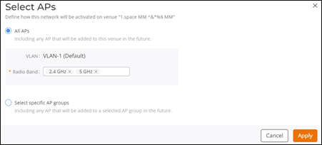
The Select APs dialog box is displayed. Select one of the following options:
- All APs: Select
All APs to
activate this network on all current and future APs in this venue. Choose a radio
band from the drop-down list. You can choose one or more of the supported radio
bands.
Select APs 
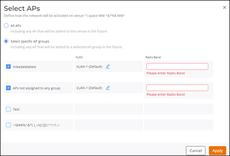
- Select specific AP
groups: Select Select specific AP
groups to activate this network on specific AP groups including any
AP that is added to the selected AP groups in the future. The APs not assigned to any
group option is displayed with a checkbox and a reminder to select
an AP Group.
Click the APs not assigned to any group checkbox; the VLAN and Radio Band options are displayed:
Select Specific AP Groups 
- In the VLAN option,
VLAN-1 is selected by default. Click the
 icon
and select VLAN or pool from the drop-down list. Depending on the selection, enter the
VLAN ID or select the pool from the drop-down list.
 - In the Radio Band option, select one or more of the supported radio bands from the drop-down list for the selected AP group.
- Click Apply.
- All APs: Select
All APs to
activate this network on all current and future APs in this venue. Choose a radio
band from the drop-down list. You can choose one or more of the supported radio
bands.
-
Click the 24/7 hyperlink in the
Scheduling
column of the Venues section on the Create New
Network page to customize the schedule.
The Schedule for Network <network-name> in Venue <venue-name> dialog box is displayed.
Schedule for Network Dialog Box 
- Click Custom Schedule.
- Customize the network schedule as
required. You can configure Monday through Sunday and times from 00:00 to 23:59.
Click the See tips hyperlink for guidance. The
Network Scheduler Tips dialog box is displayed.
Network Scheduler Tips 
- Review the tips and click OK to close the Network Scheduler Tips dialog box.
- Click Apply. The hyperlink updates to ON now. When hovered over, it displays the time until which the scheduler will remain active (<Day> <Time>).
-
Toggle the Network Tunneling switch on to
define how network traffic is tunneled at the venue. When toggled on, a Tunnel: <venue-name>
sidebar is displayed.
Note: The Network Tunneling switch is displayed only when the venue is Activated.
- Select a Tunneling Method from the drop-down.
- If you choose SoftGRE, select a
SoftGRE
profile and optionally enable and configure IPsec. (Refer to
Creating a SoftGRE Profile and Adding an SD-LAN Service).
The SD-LAN option is available only when RUCKUS Edge devices are present.
- Click Add to save and apply.
-
Click the All APs hyperlink in the
APs column or the list of
radios in the Radios column of
the Venues section on the Create New Network
page to configure APs and radio-frequency bands for the selected venue.
-
Click Next.
The Summary page is displayed.
- Review the settings that you configured.
- Click Finish.