Creating an Open Network
You can create a network that allows users to join the network without going through an authentication process.
CAUTION: RUCKUS
strongly advises against creating an open network. Wireless communication on an open
network is not secure, and information (including sensitive data, such as personal
information, credit card information, and so on) that your users send over or
through the network can easily be intercepted.
-
Click Next.
The Settings page is displayed.
Create New Network - Settings Page 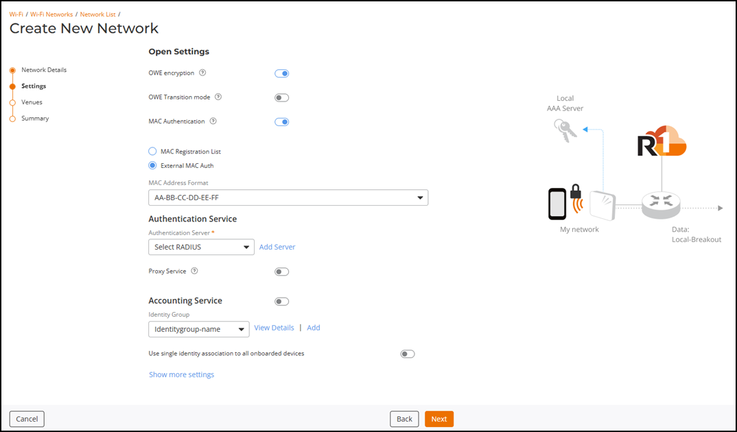
-
Identity Group:
Select an identity group from the drop‑down list.
If the identity group is not yet defined, you can create a new one; click Add, complete the fields in the Create Identity Group sidebar, and click Apply. You can then select the newly created identity group from the Identity Group drop-down list. Refer to Adding an Identity Group for information on how to create a new identity group.
You can click View Details to view the identity group details in the Identity Group sidebar.
Note:- When you select an identity group, all devices that join the network automatically become identities within that group, as shown on the Identity Group page. Users can select an existing identity group or create a new one.
- During network editing, you cannot remove the originally selected identity group; however, you can change it to a different identity group. The identity configuration section does not apply to the MAC Registration List when MAC Authentication is enabled.
- This field appears only when External MAC Auth is selected.
- If you select an Identity Group with the Auto Clean-up feature
disabled, a message appears indicating that auto clean-up is
disabled for the selected identity group, which could result in
excessive identity creation per connected client device.
Create New Network - Configuring an Identity Group for an Open Network 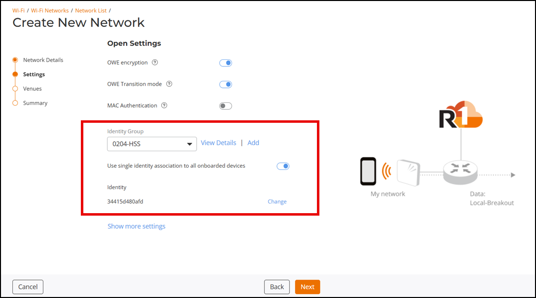
-
Click Next.
The Venues page is displayed.
Venues 
-
Select one or more venues to activate
the network by clicking the checkbox alongside the venue name, and then toggle the switch
on in the Activated
column.
The details in the APs, Radios, and Scheduling columns are displayed for all the activated venues. By default, this network configuration applies across All APs and their applicable radio bands and is scheduled to be available 24/7.Note: The Scheduling column displays availability based on the local time zone of the venue’s AP devices (for example, UTC offsets).
-
Click the All APs hyperlink in the
APs column or the list of
radios in the Radios column to
configure APs and radio-frequency bands for the selected venue.
The Select APs dialog box is displayed. Select one of the following options:
- All APs: Select
All APs to
activate the network on all current and future APs for this venue. Choose a radio
band from the drop-down list. You can choose one or more of the supported radio
bands.
Select APs 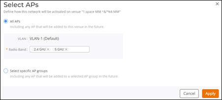
- Select specific AP
groups: Select Select specific AP
groups to activate the network on specific AP groups, including any
AP added to the selected AP groups in the future. The APs not assigned to any
group option is displayed with a checkbox and a reminder to select
an AP Group.
Click the APs not assigned to any group checkbox; the VLAN and Radio Band options are displayed:
Select Specific AP Groups 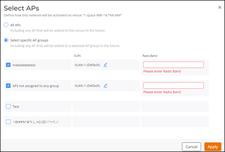
- VLAN: Select
VLAN-1,
which is selected by default. Click the
 icon,
and select a VLAN or a pool from the drop-down list. Depending on the selection, enter the
VLAN ID or select a pool from the drop-down list.
icon,
and select a VLAN or a pool from the drop-down list. Depending on the selection, enter the
VLAN ID or select a pool from the drop-down list. - Radio Band: Select one or more supported radio bands from the drop-down list for the selected AP group.
- Click Apply.
- All APs: Select
All APs to
activate the network on all current and future APs for this venue. Choose a radio
band from the drop-down list. You can choose one or more of the supported radio
bands.
-
Click the 24/7 hyperlink in the
Scheduling
column to customize the schedule.
The Schedule for Network dialog box is displayed.
Schedule for Network Dialog Box  You can choose 24/7 or Custom Schedule. Configure the following if you select Custom Schedule:
- Click Custom Schedule to
customize the network schedule as required.The Custom Schedule has Basic and Advanced tabs.Note: The venue time zone appears at the bottom of the dialog box.
- On the Basic tab, you can
configure the following:
Schedule for Network - Basic Configuration 
- Start Date:
Displays the date when the schedule begins. You can select any future date
using the date picker. The schedule always uses the local time of the AP
devices.Note: When the Start Date is today, time slots that have already passed are disabled.
- (Optional) All day: Select this option to make the network available for the entire day. When All day is selected, the From and To fields automatically disappear.
- From and
To:
These fields appear only when All day is not
selected. You can select the start and end times in 15‑minute intervals, where
the From
time ranges from 00:00 to 23:45, the To time ranges
from 00:15 to 24:00, and the To time must
always be later than the From time.Note: The selected times follow the local time of the venue’s AP devices.
- Select a repeat rule to
determine how the network availability repeats after the Start Date. The
available options are Do not repeat
(default), Repeat
Daily, Repeat Weekly, and Repeat Monthly.
Note: The Do not repeat option displays a one‑time schedule for the selected Start Date.
- End Date:
- Select None or Select date if Repeat Daily is selected. Pick an end date from the date picker when Select date is chosen.
- Select the required weekday, and then select None or Select date if Repeat Weekly is selected. Pick an end date from the date picker when Select date is chosen.
- Select a monthly
recurrence option such as a specific day of every month, the nth
weekday of every month, or the last weekday of every month,
and then select None or Select date
if Repeat
Monthly is selected. Pick an end date from the date picker
when Select
date is chosen.Note: Selecting at least one weekday is mandatory if Repeat Weekly is selected, and selecting a monthly recurrence option is mandatory if Repeat Monthly is selected.Note: Monthly options depend on whether the Start Date falls on the first through fourth weekday occurrence or the last weekday of the month. Daily, Weekly, and Monthly repeat rules deactivate the network automatically at midnight on the selected End Date.Note: If an End Date is selected, the schedule ends at midnight on that date.
- Start Date:
Displays the date when the schedule begins. You can select any future date
using the date picker. The schedule always uses the local time of the AP
devices.
- On the Advanced tab, you can
configure the following:
Schedule for Network - Advanced Configuration 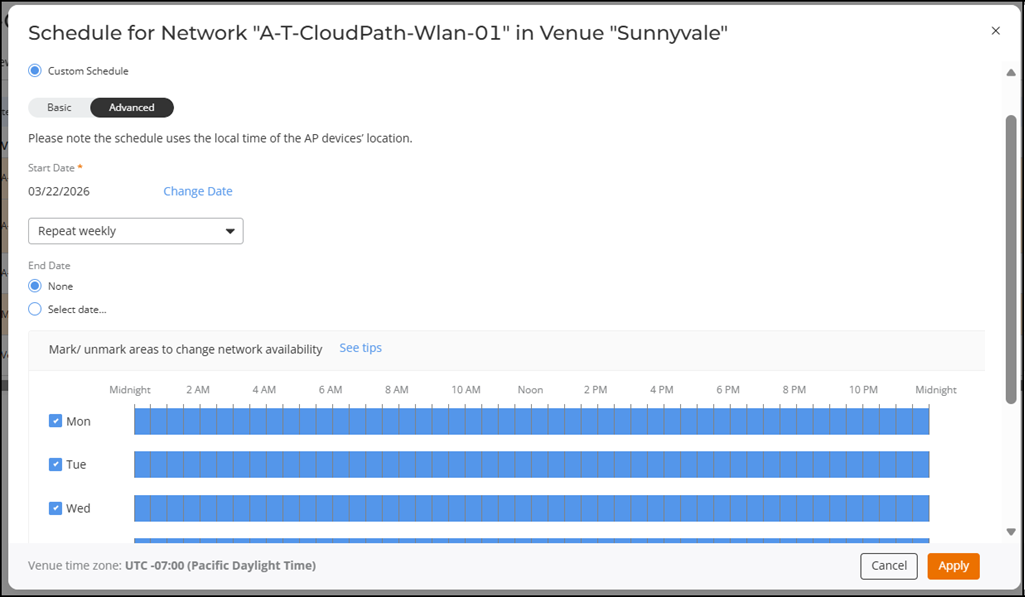
- Start Date:
Displays the date when the schedule begins. You can select any future date
using the date picker. The schedule always uses the local time of the AP
devices.Note: When the Start Date is today, time slots that have already passed are disabled.
- (Optional) Select a repeat
rule to determine how the network availability repeats after the Start Date.
The available options are Do not repeat
(default) and Repeat
Weekly. Note: The Do not repeat option displays a one‑time weekly schedule for the selected Start Date. The network automatically deactivates at the end of the last active time slot.
- End Date:
- Select None or
Select
date if Repeat Weekly
is selected. Pick an end date from the date picker when Select date is
chosen.Note: When the Start date is chosen, selecting a date from the date picker is mandatory.Note: If an End Date is selected, the schedule ends at midnight on that date.
- Select None or
Select
date if Repeat Weekly
is selected. Pick an end date from the date picker when Select date is
chosen.
- Mark the required time on the weekly grid to enable or disable network availability in fifteen‑minute intervals. You can click a single slot or click and drag to update multiple adjacent slots. A full day can be enabled or disabled using the checkbox next to each day. Dragging across a range of slots changes all slots to the opposite state of the first slot selected.
- Click See tips to view guidance on how to activate or deactivate the network for the entire day, individual time slots, or multiple adjacent time slots. The See tips option opens the Network Scheduler Tips window, which explains how to use the checkbox for full‑day selection, how to click individual slots, and how to drag across the timeline to update multiple time slots.
- Start Date:
Displays the date when the schedule begins. You can select any future date
using the date picker. The schedule always uses the local time of the AP
devices.
- Click Apply. The hyperlink displays the configured schedule, either 24/7, ON now, or OFF now. The day and time of the next change in network availability are displayed under the ON now and OFF now hyperlinks and also when you hover your cursor over the hyperlink.
- Click Custom Schedule to
customize the network schedule as required.
-
Click the All APs hyperlink in the
APs column or the list of
radios in the Radios column to
configure APs and radio-frequency bands for the selected venue.