Configuring Wi-Fi Networking Settings
RUCKUS One allows you to configure Wi-Fi networking settings, such as LAN ports for your APs, Mesh networking, Directed Multicast, Cellular options (in venues with M510 APs), Smart Monitor, and RADIUS service, at the venue level.
-
Select the Wi-Fi
Configuration tab and Networking
sub-tab.
The Networking sub-tab is displayed. The Networking sub-tab provides several options for configuration, all of which can be accessed by clicking the menu option on the left, or by scrolling down the screen.
Note: Cellular Options is available only if you have the M510 AP model in your venue.Within the Networking sub-tab, customize the services of your preference and click Save. Refer to the following instructions to configure each of the available networking services:
- Configuring LAN ports
- Configuring a Mesh network
- Configuring Directed Multicast
- Configuring Cellular Options
- Configuring Smart Monitor
- Configuring RADIUS Service
Networking Configuration 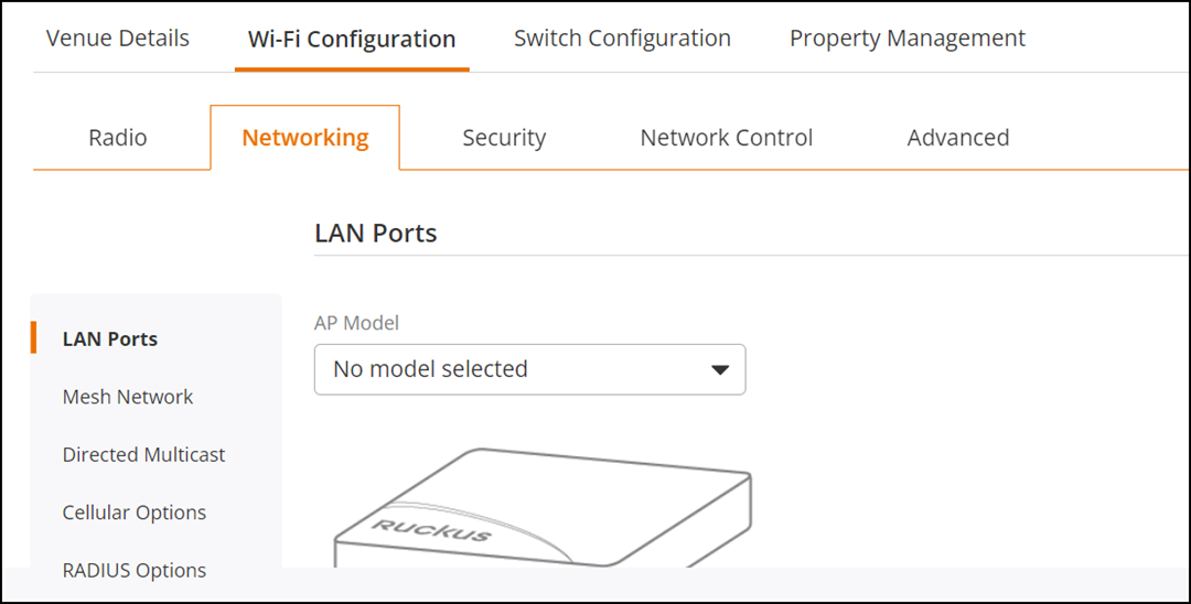
Configuring the LAN Ports
-
Configure the LAN ports for
specific AP models. Select an AP from the AP Model
drop-down list and configure the following. The screen refreshes, displaying
configuration options (per LAN sub-tab) and an image of the selected AP with
the ports labeled.
Note: By default, LAN 1 is applicable for all the AP models and additional LANs are available as applicable to the AP model. For example, the T300 AP has only one LAN port, the R600 model has two LAN ports, and the H550 model has five LAN ports.
LAN Ports Settings 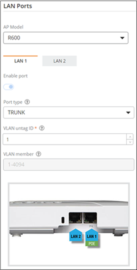
-
Configure the following
settings:
Note: The PoE Operating Mode and Enable PoE Out settings apply to the entire AP. All remaining options are configured independently on each LAN sub-tab.
- PoE Operating Mode: Select the PoE Operating Mode (for specific AP models only) from the drop-down list. By default, Auto is selected. The other options are model-specific, such as: 802.3af, 802.3at, or a specific class of 802.3bt.
- Enable PoE Out: By default, the Enable PoE Out option is disabled. You can enable this option by toggling the Enable PoE Out switch on. This option is available for specific AP models only.
- Enable port: By default, Enable Port is activated for all LAN ports, but you can disable this option by toggling the Enable Port switch.
- Ethernet Port
Profile: Manages the configuration settings for
Ethernet ports on networking devices. Select an Ethernet port
profile from the drop-down list or click Add
Profile to create a new Ethernet port profile. Refer
to Ethernet Port Profile for more
information.Note: For AP firmware 7.0.0.200.6290 and later versions, any changes to the trunk port VLAN untag ID will take effect. However, for APs with firmware versions earlier than 7.0.0.200.6290, the trunk port VLAN untag ID will remain at the default value of 1, even if the configuration has been changed.
- Enable SoftGRE
Tunnel: Tunnels the traffic to a SoftGRE gateway.
Toggle the Enable SoftGRE Tunnel switch to on to enable the
feature. Select a SoftGRE profile from the SoftGRE
Profile drop-down list or click Add
Profile to create a new SoftGRE profile. Refer to
Creating a
SoftGRE Profile for more information.Note: The uplink port does not support SoftGRE tunneling, which will cause the AP(s) to disconnect.Note: SoftGRE tunnel is not supported if you select an Ethernet port profile with 802.1X Role as Supplicant. If SoftGRE tunnel is already enabled and you switch to a profile with the 802.1X Supplicant role, then SoftGRE tunnel will be automatically disabled.Note: There is no alternative keep-alive detection mechanism between the AP and the SoftGRE server other than ping. As a result, if the primary SoftGRE service goes down but the ping to its IP address still succeeds, then the AP will not fail over to the backup gateway.
- Enable
IPsec: Encapsulates data packets within GRE packets
and secures them using IPsec. This option is disabled by default and
available for configuration only when the SoftGRE
Tunnel option is enabled. Toggle the Enable
IPsec option to enable this feature. Select an IPsec
profile from the IPsec
Profile drop-down list or click Add
Profile to create a new IPsec profile. Refer to
for more information.Note: A venue supports up to three SoftGRE-activated profiles without IPsec or one SoftGRE profile with IPsec. If a LAN port already has SoftGRE enabled, click the toggle to disable SoftGRE tunneling before enabling SoftGRE with IPsec. Similarly, if SoftGRE with IPsec is enabled, click the toggle to disable SoftGRE with IPsec before enabling SoftGRE tunneling.Note: When an Ethernet LAN port for an AP is enabled and configured with both SoftGRE and IPsec, all the wired clients connected to the customized AP LAN port are directed to the SoftGRE tunnel, protected by IPsec.
- DHCP Option
82: DHCP Option 82 allows a DHCP relay agent to
insert circuit-specific information (such as port or MAC address)
into DHCP packets before forwarding them to the DHCP server. This
enables the server to assign IP addresses based on client location
or relay source. In RUCKUS One,
this feature is supported for wireless clients or for wired clients
connected via AP LAN ports. By default, this feature is disabled.
Toggle the DHCP Option 82 switch on to enable this setting.
After enabling DHCP Option
82, configure at least one of the following
sub-options: Note: DHCP Option 82 cannot be enabled unless at least one sub-option is enabled.
- Agent Circuit ID
(#1): Click the toggle to enable this option, then
select how the AP interface or port is identified from the drop-down
list.
DHCP Option 82 Sub Options 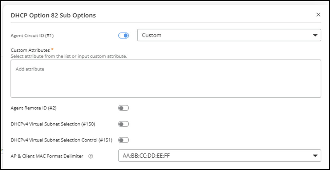
- Custom
Attribute: Click Add attribute to
access the drop-down list of system-defined attributes. This field
appears (and is mandatory) only when you select
Custom as the Agent Circuit
ID. Note: You can add up to eight custom attributes, including user-defined attributes. The system separates multiple attributes by inserting a colon (:) between each. Use only letters (a–z, A–Z) and numbers (0–9), with a maximum length of 24 characters per attribute. Click the
 icon to add each attribute. Each
attribute can be added only once.
icon to add each attribute. Each
attribute can be added only once. - Agent Remote ID (#2): Click the toggle to enable this option, then select the identifier for the AP forwarding the DHCP request from the drop-down list.
- DHCPv4 Virtual Subnet Selection (#150): Click the toggle to enable or disable this setting to define whether a virtual subnet should be used for IP address assignment.
- DHCPv4 Virtual Subnet Selection Control (#151): Click the toggle to enable this option, then select and configure how the virtual subnet is applied. Options include Area and ESSID. If you select Area, a text field appears where you can enter the area name (1 to 26 characters).
- AP and Client MAC Format Delimiter: Choose the syntax used to format MAC addresses. Options include AA:BB:CC:DD:EE:FF (the default), AA-BB-CC-DD-EE-FF, and AABBCCDDEEFF.
- Click Apply to save your configuration.
- Agent Circuit ID
(#1): Click the toggle to enable this option, then
select how the AP interface or port is identified from the drop-down
list.
- Client
Isolation: Enabling client isolation enhances
network security by preventing devices on the same Wi-Fi network
from communicating directly with each other. To apply client
isolation, a manual device reboot is necessary. You can choose the
specific AP devices from the AP list and click Reboot to restart them.Note: Enabling client isolation on the uplink will disconnect the AP.
- Isolate Packets: When Client Isolation is enabled, you can also isolate data wired client packets within the network to enhance network security and performance by controlling how data is transmitted and received within the network. Select the packet type from the drop-down menu. Isolating Unicast packets prevents direct communication between individual devices on the same network. Isolating Multicast/broadcast packets prevents specific devices from receiving data from the same device unless explicitly allowed. Isolating Unicast and multicast/broadcast packets prevents all devices from receiving data from one device.
- Automatic support for VRRP/HSRP: When Client Isolation is enabled, you can also enable Automatic support for VRRP and HSRP, ensuring seamless failover and increased network reliability by dynamically managing router failover without manual intervention. This maintains high availability and reliability in critical network environments.
- Client Isolation
Allowlist: Enabling Client
Isolation on a specific port for an AP model at a particular
venue prevents devices on the same network from communicating with
each other. However, the Client Isolation
Allowlist permits certain devices to bypass this restriction
and communicate with isolated clients. You can select an allowlist
from the drop down menu or click Add
Policy to create one. These policies allow specific
devices to communicate with isolated clients despite the isolation
settings.
To create a policy, provide the Policy Name, Description and add clients to the policy from the Select from Connected Clients. You can also add clients by clicking Add New Client. Click Policy Details to view information about the policy.
- (Optional) If you want to revert to the default port settings, click Reset to default. A confirmation message is displayed, click Continue. Modifications to the LAN port settings at the venue level are specific to each AP model, meaning any change or reset will only affect the selected AP model. Depending on the AP model, the following configurations will be reset to their default settings: PoE Operating Mode, Enable Port, Ethernet Port Profile, Enable SoftGRE Tunnel, and Client Isolation.
Configuring a Mesh Network
-
(Optional) Enable and
configure Mesh networking. Go to the Mesh Network
portion of the screen.
Mesh networking adds resiliency to your venue network by ensuring that wired APs in your venue maintain a connection to the network if they lose their wired connection and allows APs to be added to a network even if it is physically prohibitive to cable them to the network.
Attention: Once enabled and Mesh-enabled APs are assigned to this venue, you cannot disable the Mesh Network option.Attention:The Mesh Network cannot be activated on a Venue where DHCP or Client Isolation settings are enabled.
Mesh Network Settings 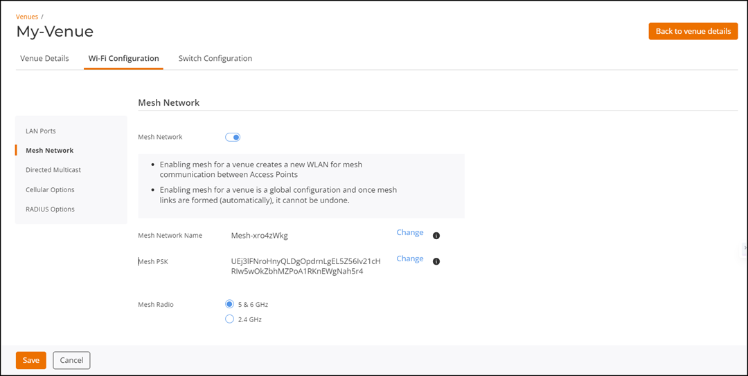
Configuring Directed Multicast
-
Select one from the
following options:
- Wired Client: This option controls multicast-to-unicast conversion from wired clients on a non-trunk interface.
- Wireless Client: This option controls multicast-to-unicast conversion from wireless clients.
- Network: This option controls multicast-to-unicast conversion from wired clients on a trunk interface.
Directed Multicast Settings 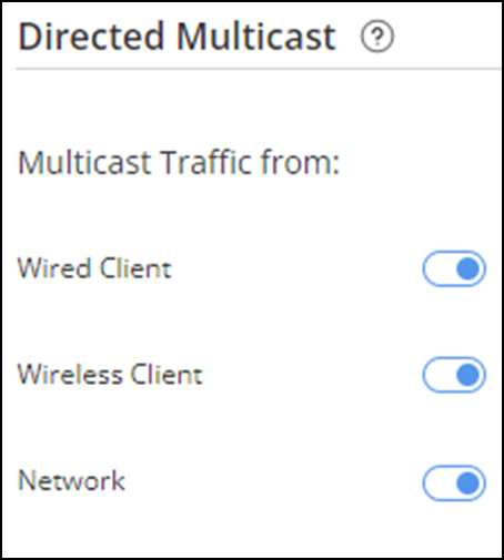
When Directed Multicast is enabled for any of these options, the AP inspects multicast traffic and monitors client IGMP/MLD subscriptions to determine packet handling. For multicast data that the wireless clients of the AP are subscribed to, the AP will convert packets to unicast. When no client is subscribed, the AP will drop the packets. Some well-known traffic types (Bonjour, uPnP, and so on) will bypass this logic altogether; the multicast-to-unicast conversion is determined by the Directed MC/BC Threshold value configured in the Wi-Fi network's Networking settings (refer to Configuring Additional Settings for a Wi-Fi Network for more information).
Configuring Cellular Options
-
Configure the following
settings (fields are identical for both the 1 Primary SIM
and 2 Secondary
SIM sections, but are configured independently).
By default, both 1 Primary SIM and 2 Secondary SIM are enabled. Use the toggle button to disable or re-enable the options.Note: At least one SIM slot (Primary or Secondary) must be enabled.
Cellular Options Settings 
- APN: Enter the APN name.
- 3G/4G (LTE) Selection: By default, Auto is configured. You can select either 4G (LTE) only, 3G only, or Auto.
- Data Roaming: By default, data roaming is enabled. Use the toggle button to disable or re-enable the options.
- LTE Band Lock: Select the bands for 3G and 4G for the Venue's current country. Click Show band for other countries to view the available bands for other Domain 1 and Domain 2 countries, and Japan.
- Select the WAN
Connection.
- Ethernet (Primary) with cellular failover
- Cellular (Primary) with Ethernet failover
- Ethernet Only
- Cellular Only
- Set the Primary WAN Recovery Timer. The default value is 60 seconds. Valid values are from 10 through 300 seconds.
Configuring Smart Monitor
- Manage Smart Monitor settings at the venue level. Go to the Smart Monitor portion of the screen.
- Toggle the switch on to monitor all the APs in the Venue. By default, Smart Monitor is disabled.
-
Configure the
settings:
- Heartbeat Interval: Indicates the time interval at which an AP sends a heartbeat (arping) to confirm its reachability to the default gateway. Valid values are 5 through 60 seconds, default is 10 seconds.
- Max Retries: Indicates the maximum number of failed connection attempts after which the gateway is considered unreachable. Valid values are 1 through 10, default is 3 retries.
Configuring RADIUS Service
-
Configure RADIUS services at
the venue level. Go to the RADIUS
Service portion of the screen.
The following configuration options are available for venue-level customization of RADIUS services:
Selecting RADIUS Service 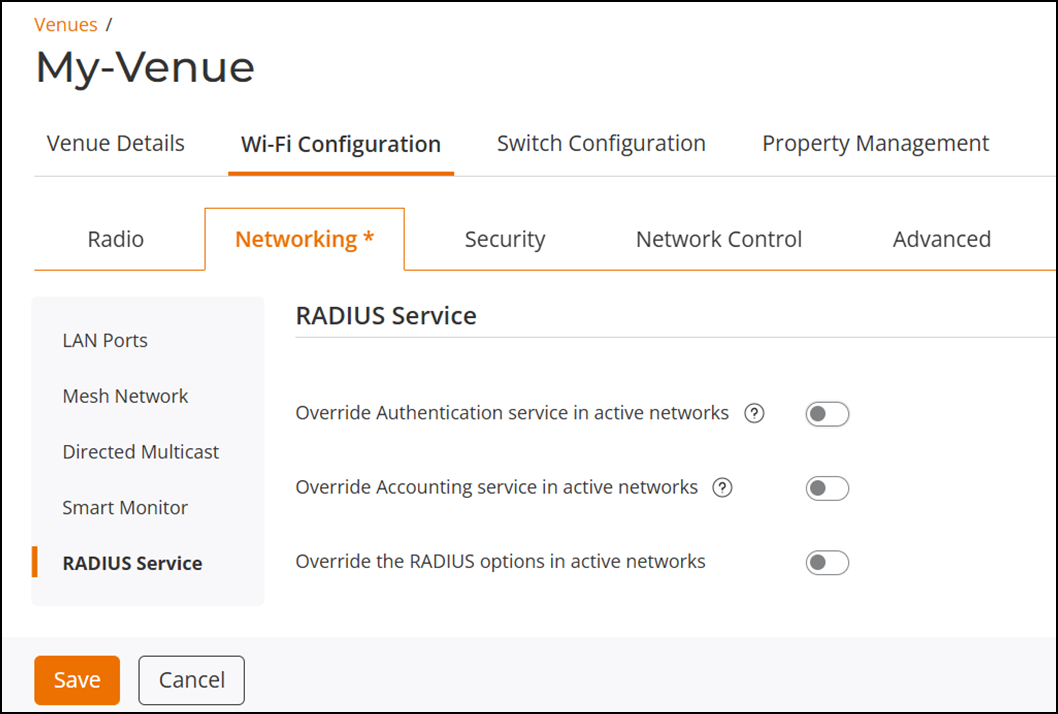
- Override Authentication service in active networks - Allows you to specify a custom authentication service for active networks.
- Override Accounting service in active networks - Allows you to specify a custom accounting service for active networks.
- Override the RADIUS options in active networks - Enables customization of additional RADIUS parameters for active networks.
Note: RADIUS profiles configured with FQDN are not supported. Only non‑proxy mode is available, and the dropdown list will exclude such profiles.Note:- By default, RADIUS services are disabled.
- While custom RADIUS profiles can be configured for Authentication and Accounting services, applying a custom venue RADIUS profile is not supported on Hotspot 2.0 networks.
- Only non-proxy Authentication or Accounting servers will be overridden.
- If you disable the override option for Authentication, Accounting, or RADIUS, the original RADIUS server settings will be restored for those networks.
-
Configure the
settings:
-
Add
Server: Click Add
Server to add a new RADIUS authentication server.
Enabling Override Authentication Service 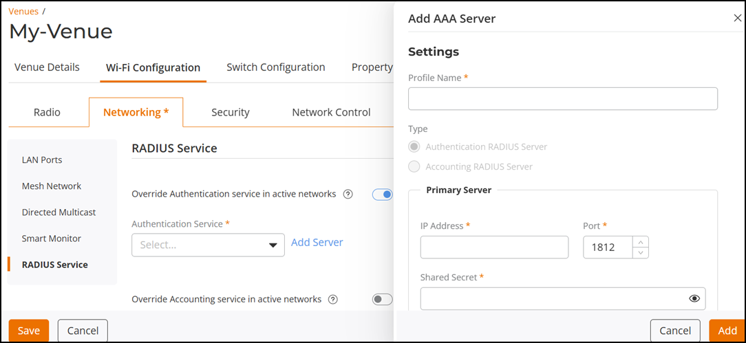 In the Add AAA Server sidebar, under Settings, configure the following:
- Profile Name: Enter a unique name for the server profile.
- Type: By default, the type is automatically selected based on the service being configured—either Authentication or Accounting.
- In the Primary
Server sub-section, configure the following:
- IP Address: Enter the IPv4 or IPv6 address of the RADIUS server.
- Port: Optionally, modify the default port number (1813) to a number from 1 through 65535.
- Shared
Secret: Enter the shared secret key.Note: The Shared Secret key must be a string of 1 to 255 standard ASCII characters, including letters, numbers, symbols, and space. It cannot consist entirely of spaces and must start and end with a non-space character.
- Optionally, click Add Secondary Server. Then repeat the steps for entering the IP Address, Port, and Shared Secret as described previously.
- Click Add to save the server profile.
-
Add
Server: Click Add
Server to add a new RADIUS authentication server.
-
Configure the
settings:
-
Add
Server: Click Add
Server to add a new RADIUS accounting server.
Enabling Override Accounting Service 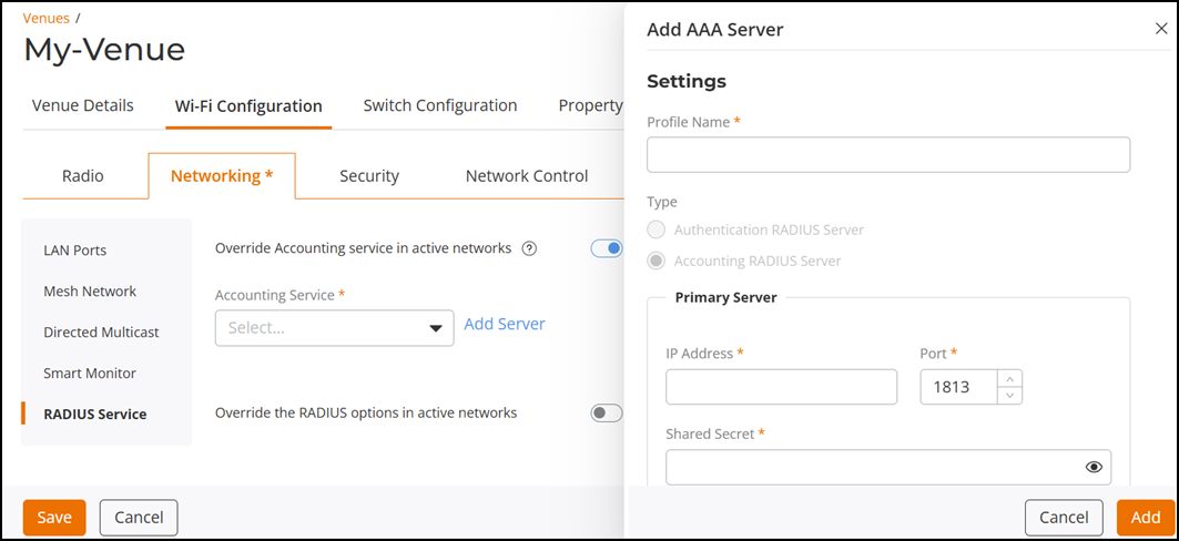 In the Add AAA Server sidebar, under Settings, configure the following:
- Profile Name: Enter a unique name for the server profile.
- Type: By default, the type is automatically selected based on the service being configured—either Authentication or Accounting.
- In the Primary
Server sub-section, configure the following:
- IP Address: Enter the IPv4 or IPv6 address of the RADIUS server.
- Port: Optionally, modify the default port number (1813) to a number from 1 through 65535.
- Shared
Secret: Enter the shared secret key.Note: The Shared Secret key must be a string of 1 to 255 standard ASCII characters, including letters, numbers, symbols, and space. It cannot consist entirely of spaces and must start and end with a non-space character.
- Optionally, click Add Secondary Server. Then repeat the steps for entering the IP Address, Port, and Shared Secret as described previously.
- Click Add to save the server profile.
-
Add
Server: Click Add
Server to add a new RADIUS accounting server.
-
Configure the
settings:
Enabling Custom RADIUS Options 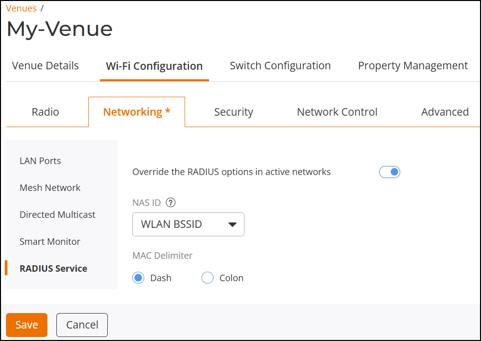
- NAS ID: Defines the ID sent to the RADIUS server, which will identify the AP. Select the appropriate option from the menu; options include WLAN BSSID (default selection), Venue Name, AP MAC, AP Group Name and User-defined. Note that selecting User-defined prompts you to define a Custom NAS ID.
- MAC Delimiter: Select either Dash or Colon for the MAC Delimiter. This option appears for the NAS ID types WLAN BSSID and AP MAC.
- NAS Request Timeout: Indicates the duration after which an expected RADIUS Response message is considered to have failed. Valid values are 2 through 20 seconds, default is 3 seconds.
- NAS Max Retries: Indicates the maximum number of failed connection attempts after which the controller will failover to the backup RADIUS server. Valid values are 2 through 10 retries, default is 2 retries.
- NAS Reconnect Primary: Indicates the time interval after which the controller will recheck if the primary RADIUS server is available when the controller has failed over to the backup RADIUS server. Valid values are 1 through 300 minutes, default is 5 minutes.
- Called Station ID: Indicates the format for the called station ID, which is sent to the RADIUS server as an attribute, and can be used in policy decisions. Select the appropriate option from the menu; options include WLAN BSSID (default selection), AP MAC, AP Group, and None.
- Single Session ID Accounting: Enable this feature to allow the APs to maintain one accounting session (including statistics) for a user roaming between APs. Disabled by default. Toggle the switch to on to enable the feature.