The default radio settings for the venue
can be adjusted to meet the administrator’s needs. Additionally, the external antenna
settings, load balancing, and client admission control can be modified.
Complete the following steps to customize the radio
settings for a venue.
On the navigation bar, click
Venues.
The Venues page is displayed.
Select the check box for a
specific venue and click Edit.
Alternatively, click a specific venue name then click the Configure
button.
Select the Wi-Fi
Configuration tab.
By default, the
Radio tab and Wi-Fi Radio sub-tab
are displayed. The Wi-Fi Radio sub-tab provides several
options for configuration, all of which can be accessed by clicking the menu
option on the left, or by scrolling down the screen. Customize your preference
and click Save. Refer to the following instructions to configure each of
the available radio services:
The 2.4 GHz, 5 GHz, and 6 GHz radio
settings, although similar, must be configured separately.
RUCKUS One allows for per-radio customization
on access points. You can choose to use the venue settings for each
radio or configure them individually.
For Wi-Fi 6/7 band
management, click Add Model. In
the Wi-Fi Band Management sidebar, select the
Model using the drop-down menu and Band Operation
Mode (Dual-band or
Tri-band). Dual-band is for 2.4 and 5 GHz bands, and
tri-band is for 2.4, 5, and 6 GHz bands. For more information, refer to
Switchable Radio Frequency Support.
Note: Only AP models that
support band management are included in the drop-down menu and can be
configured (such as R670, T670, and R760 APs).
A warning message
"Modifying the band operation mode will reboot the AP and the Mesh
connection will also be disconnected when rebooting" is displayed. Click
Add to add the AP model.
Venues - Wi-Fi
Configuration - Configuring Wi-Fi Radio
Select a radio from the
following options: 2.4 GHz, 5 GHz, or 6 GHz.
Configure the following
settings for the 2.4 GHz, 5 GHz, and
6 GHz bands:
Channel Selection
Method: Select either Background
Scanning,
ChannelFly, or Manual channel
selection.
Channel
Change Frequency: This option is displayed only if
you select the Channel Selection Method as
ChannelFly. Adjust the frequency between
1-100. By default, 33 is selected.
Run background scan
every [ ] seconds: If you selected Background Scanning, interval at which
RUCKUS One
runs the scan ranges from 1 through 65535 seconds. For 2.4 GHz and 5
GHz, the default is 20 seconds.
Bandwidth: Select Auto,
20
MHz, or 40
MHz channel width for the 2.4 GHz radio, or
Auto, 20
MHz, 40
MHz, 80
MHz, or 160
MHz channel width for the 5 GHz radio, or Auto,
20
MHz, 40
MHz, 80
MHz, 160
MHz, or 320
MHz channel width for the 6 GHz radio.
Transmit Power
Adjustment: Select the transmit power adjustments
from the drop-down list. The default setting is Full.
Channel Selection: A blue icon above the
channel number indicates that the channel is enabled for the radio.
If there are channels that you do not want the radio to use, disable
them by clicking their respective icons. When a channel is disabled,
its blue icon changes to gray.
Note: For the 5 GHz,
Lower 5 GHz, and Upper 5 GHz bands, you must configure a
different set of channels for indoor APs and outdoor
APs.
Note: For 6 GHz bands, the channel range for both indoor and outdoor
Access Points (APs) can be configured individually to
distinguish indoor and outdoor channel ranges, considering the
diverse channel availability across different counties. APs
located within the venue can adopt these indoor or outdoor
channel configurations based on their model’s capabilities,
provided they are set to use the venue’s settings.
(Optional) Toggle Use same channel for
indoor and outdoor APs to on. This option is available
depending on the country code; different countries have specific regulations
regarding which channels can be used for indoor and outdoor APs.
Allowing Outdoor
APs to Use Indoor ChannelsWhen this feature is enabled, outdoor APs can use indoor
channels.
To enable the Automated
Frequency Coordination (AFC) feature, select the 6 GHz
option and then toggle the Enable Indoor
AFC switch to ON. For outdoor APs, AFC is automatically
enabled.
Note:
The AFC feature
is disabled by default for existing venues upgraded from an
earlier version (for example, 6.2.x). Conversely, the AFC
feature is enabled by default for new venues created in version
R7.0.
The AFC feature
is available for venues only if the country of the selected zone
allows AFC or RUCKUS
obtains the AFC certificate from a competent government
authority, such as the US Federal Communications Commission
(FCC). For any other locations, the Enable Indoor
AFC option is grayed out.
In the 6 GHz band (ranging
from 5.925 to 6.425 GHz and from 6.525 to 6.875 GHz) that houses various
radio services, Wi-Fi access points (APs) use the AFC system to share
radio waves without causing interference, improving the overall network
performance. The AFC system manages and allocates frequencies
dynamically, utilizing a database of 6 GHz operators (including
geolocation, frequencies, power levels, antenna coverage) that track
frequencies already in use in a specific area. By checking the AFC
database, Wi-Fi APs can avoid using frequencies that are already
occupied, preventing signal disruptions.
When you enable the AFC
feature on RUCKUS One, a
standard power (SP) AP (tri-radio, outdoor AP), before transmitting,
consults with a local AFC system to validate frequency operation and
starts operating only after the usage request is approved. However, an
AP operating in Low Power Indoor (LPI) mode is allowed to transmit
without the need for approval from the AFC system. For more information,
refer to the RUCKUS
AFC User Guide.
Enabling the AFC
Feature
After enabling the
AFC feature, you must configure the AFC Venue
Height. Enter the floor numbers in the corresponding
fields.
The US FCC mandates
the AFC geolocation to determine the permissibility of transitioning
to substitution-permutation in specific channels. The identification
of the geographic location of a device is based on various data
collected from different areas of the same place. Therefore, after
enabling the AFC feature and configuring the AFC venue height, set
the GPS coordinates using the RUCKUS One
mobile app. The RUCKUS One
mobile app is available for download from Apple App Store and Google
Play Store. Scan the following QR code to download the RUCKUS One mobile app on your mobile device.
Android Devices
iOS Devices
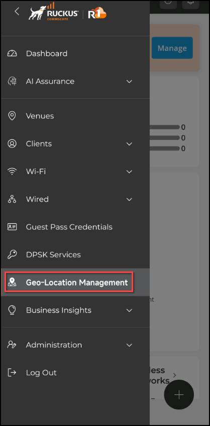
Log in to the RUCKUS One mobile app and select the Geo-Location
Management menu option.
Geo-Location Management (RUCKUS One Mobile App)
Note: RUCKUS Wi-Fi 6E
APs do not have an embedded GPS; their location must be set
using the RUCKUS One mobile app. If the AFC geolocation for Wi-Fi 6E/7
APs is configured using the RUCKUS One mobile app, it takes precedence over the GPS
location detected by the AP. After powering up, the AP might
take up to 30 minutes to scan all its neighbors and use the
neighbor list to calculate the AFC geolocation.
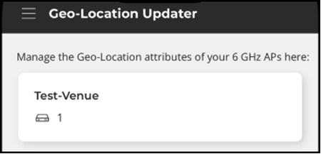
From the
Geo-Location Updater screen, select a
Venue.
Geo-Location Updater (RUCKUS One Mobile App)
Place the mobile
phone close to the AP and ensure your device can receive signals
from the AP.
Log into the RUCKUS One mobile app again with your account and register
the geolocation to your AP.
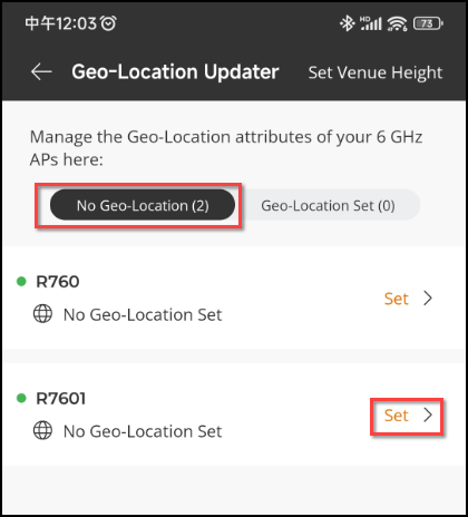
Select the
Geo-Location Management menu
APs in the selected
venue, without the geolocation coordinates, are listed in the
No
Geo-Location tab.APs
Without Geolocation Coordinates (RUCKUS One Mobile
App)
To set the
geolocation, click Set
next to an AP.
The AP details
screen is displayed.AP Details
Page (RUCKUS One Mobile App)
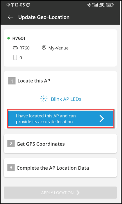
Complete the
following steps to locate and get GPS coordinates.
In the Step 1
(Locate
this AP) tile, click Blink AP
LEDs. The LED light in the respective AP
starts blinking. This is to help you identify the device for
which you would need to set the geolocation.
After
identifying the AP, click I have
located this AP and can provide its accurate
location. A check mark appears and the
wizard proceeds to the next Step (Get GPS
Coordinates) tile.Locating the AP (RUCKUS One Mobile App)
Move your
mobile device as close as practicable to the AP. You can
view the GPS location in the Google map displayed in the
Step 2 (Get GPS
Coordinates) tile.
After
verifying the location on the Google map, click GPS
coordinates have been set. A check mark
appears and the wizard proceeds to the Step 3 (Complete
the AP Location Data) tile.Getting GPS Coordinates (RUCKUS One Mobile
App)
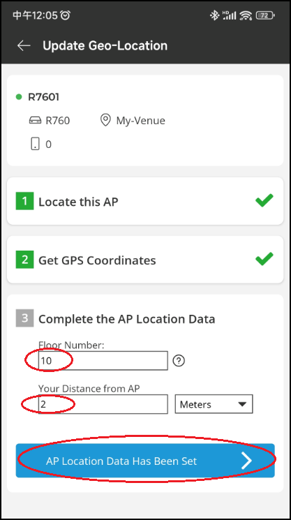
In the Step 3
(Complete
the AP Location Data) tile, enter the Floor
Number, enter Your
Distance from AP, and select the distance
unit of measure.AP
Location - Floor Number and Your Distance (RUCKUS
One Mobile App)
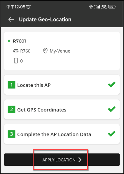
Click AP Location Data
Has Been Set. A check mark appears and the
Apply
Location button becomes active.
Click APPLY
LOCATION.
The
geolocation settings are applied to the AP.Applying
Location Settings (RUCKUS One Mobile App)
Ensure that the
geolocation setting has been applied to your AP successfully. The AP
will be moved to the Geo-Location
Set tab and the status of the AP will be set to
Manual.
Geo-Location Status Change to Manual (RUCKUS One Mobile
App)
Complete the following fields to configure 6 GHz
band.
Channel selection
method: By default, ChannelFly
is selected.
Channel Change
Frequency: This option is displayed only if you
select the Channel Selection Method as
ChannelFly. Adjust the frequency between
1-100. By default, 33 is selected.
Run background scan every [ ]
seconds: If you selected Background Scanning, interval at which RUCKUS One will run the scan. The interval
ranges from 1 through 65535 seconds. For 2.4 GHz and 5 GHz, the
default is 20 seconds. For 6 GHz, the default is 10 seconds.
Bandwidth: Select
Auto, 20 MHz,
40 MHz, 80 MHz,
160 MHz, or 320
MHz channel width from the drop-down list.
Transmit Power Adjustment: Select
the transmit power adjustments from the drop-down list. The default
is Full.
BSS Min Rate: Select HE MCS
0, HE MCS 1, HE MCS
2, or HE MCS 3 from the
drop-down list.
Mgmt Tx Rate: Select 6
Mbps, 9 Mbps, 12
Mbps, 18 Mbps, or 24
Mbps from the drop-down list.
Channel
Selection: A blue icon containing the channel number
indicates that the channel is enabled for the radio. If there are
channels that you do not want the radio to use, disable them by
clicking their respective icons. When a channel is disabled, its
blue icon changes to gray.
(Optional) Click Reset to Default Settings to revert
to default settings.
Configuring Load Balancing
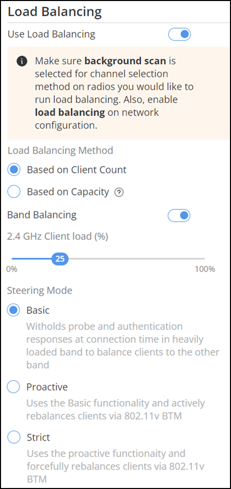
Note: Make sure Background
Scanning is selected for Channel selection
method on the radios for which you would like to enable
Load Balancing. Also, at the Wi-Fi network level,
enable Load Balancing on network configuration (More Settings > Radio > Load Control options).
Select the Load
Balancing sub-tab and toggle the Use Load
Balancing switch to ON. By
default, Load Balancing is set to
OFF.
Load Balancing
Sub-tab
For Load
Balancing Method, choose one of the following methods:
Based on
Client Count (default): Distributes clients evenly
across APs by considering the number of connected devices.
Based on Capacity: Allocates clients to APs
based on their available capacity, which includes factors such as
bandwidth, data rate, and the number of streams. Choosing this option
will hide the Band Balancing setting from the
user interface.
Toggle the Sticky Client
Steering switch to ON and
configure the following settings:
By default, Sticky Client
Steering is disabled.
Note: You must enable the
Use Load
Balancing option to configure the Sticky Client
Steering setting.
SNR
Threshold (dB): The Signal-to-Noise Ratio (SNR)
threshold is a value that determines the minimum acceptable SNR for
a client device to maintain a connection with an AP. Enter a
threshold value ranging from 5 to 30. The default value is 15.
Neighbor
AP (%): The Neighbor AP threshold is a value that
represents the minimum acceptable percentage of signal strength from
neighboring APs compared to the current AP. Enter a threshold value
ranging from 10 to 40. The default value is 20.
Note: If you disable Load
Balancing, Sticky Client Steering
feature on all the APs in the venue will be deactivated.
Toggle the Band Balancing switch to
ON. Move the slider to configure the 2.4 GHz Client load percentage. By default,
Band Balancing is enabled.
Band Balancing typically distributes clients between different frequency
bands (2.4 GHz, 5 GHz, and 6 GHz) to avoid congestion on a single
band.
Select a Steering
Mode from the following options:
Basic
(default): Delays probe and authentication responses during connection
time in a heavily loaded band to balance clients to the other
band.
Proactive: Uses the Basic functionality and actively
rebalancing clients using IEEE 802.11v BSS Transition Management
(BTM).
Strict:
Uses the Proactive functionality and forcefully rebalances clients using
IEEE 802.11v BTM.
Note:Sticky
Client Steering requires the clients to support IEEE
802.11v for optimal operation. In Strict mode for
non-802.11v clients, the Sticky Client Steering algorithm will send an
IEEE 802.11 disassociation message to the client to force the client to
scan for neighboring APs with a better potential service.
The following table
specifies the client behavior on different steering modes:
Client Type
Basic
Proactive
Strict
Non-802.11v
No steering actions are taken
No steering actions are taken
The client is disconnected from the current AP if it
does not move to a better AP.
802.11v
The BTM frame is sent, allowing the client (STA) to
decide whether to move to a better AP.
The BTM frame is sent, allowing the client (STA) to
decide whether to move to a better AP.
The BTM Disassoc-imminent option is used, notifying a
client device that it must move to another AP within a
specified time, or it will be disassociated from the
current AP.
Configuring Client Admission Control
Disable Load Balancing and Band
Balancing at the venue level to enable Client Admission Control. By
default, Client Admission
Control is disabled.
Toggle the Enable 2.4 GHz and Enable 5
GHz switches to ON.
You can apply the Client
Admission Control setting on different frequency bands
separately to manage client access and performance.
Configure the following settings:
Min. client count: The minimum number of
clients that must be connected to a venue ensuring Client Admission
Control is enforced only when there are sufficient number of
clients, avoiding unnecessary restrictions during light network
load. Select a value ranging from 0 through 100.
Min. radio load (%): The minimum percentage
of radio load (utilization) required to manage network resources
effectively. Select a value ranging from 50 through 100.
Min. client throughput (Mbps): The minimum
throughput that each client must achieve to maintain a minimum
performance standard for connected clients by restricting new
connections if throughput drops below the threshold. Select a value
ranging from 0 through 100.
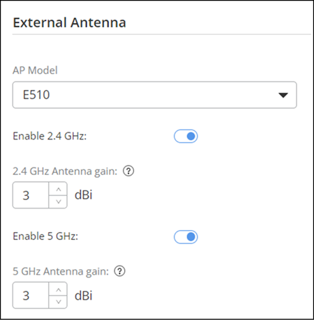
Configuring the Antenna
Select the
Antenna sub-tab.
Select the AP Model from
the drop-down list. Depending on the AP model, configure the following
parameters:
E510: Toggle the Enable 2.4
GHz and Enable 5 GHz
switches to ON. Specify the antenna gain for 2.5 GHz and 5 GHz as
specified in the antenna data sheet and then click Save.
T350SE: Toggle the Enable
switch to ON.
Configure the 2.4 GHz Antenna gain and
5 GHz Antenna gain as specified in
the antenna data sheet and then click Save.
T750SE: Toggle the Enable
switch to ON.
Specify the parameters for 2.4 GHz Antenna
gain and 5 GHz Antenna
gain as specified in the antenna data sheet and then
click Save.
T670SN: Select the
Antenna Type. Options include Sector
and Narrow.