From the RUCKUS One web interface, you can view the routed interfaces of a switch.
Routed interfaces are network ports designed to function at
Layer 3 (the network layer) of the OSI model, allowing them to execute routing tasks.
They can transmit packets based on IP addresses, making routing choices to guide traffic
between various networks. Typically, they are set up with an IP address and subnet mask,
enabling them to engage in IP routing.
Routed interfaces are utilized to link different networks, such as connecting a
router to a switch or bridging two routers. They can also be employed in multilayer
switches to facilitate routing between Virtual Local Area Networks (VLANs). These
interfaces offer enhanced control over traffic management and can support
sophisticated routing protocols like Open Shortest Path First (OSPF), Border Gateway
Protocol (BGP), and Enhanced Interior Gateway Routing Protocol (EIGRP).
The ICX 8100, ICX 8100‑X, and ICX
8100 AV models are supported. The following limitations apply:
Routed interfaces (VEs) are
supported on firmware 10.0.10h and later.
Only the default VE interface is
supported on firmware versions earlier than 10.0.10h.
In firmware 10.0.10h and later
(excluding the 10.0.20 series), up to 512 VE interfaces are supported.
Complete the following steps to view the routed interface of a switch:
On the navigation bar, select
Wired >
Switches > Switch
List.
The
Switches page is displayed, defaulting to the
Switch List tab.
Click the name of the switch to
view its routed interface configuration.
The switch detail page is displayed,
defaulting to the Overview tab.
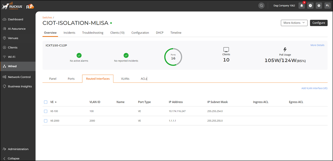
Select the Routed Interfaces
sub-tab to view the routed interfaces.
Routed
InterfacesThe page displays the following information:
VE: Displays the VE interface identifier (for
example, VE‑100).
VLAN ID: Displays the VLAN associated with the VE
interface.
Name: Displays the configured name of the
interface.
Port Type: Displays VE, indicating a
virtual routed interface.
IP Address: Displays the IP address assigned to
the interface.
IP Subnet Mask: Displays the subnet mask
associated with the IP address.
Ingress ACL: Displays the ACL applied to incoming
traffic.
Egress ACL: Displays the ACL applied to outgoing
traffic.
(Optional) Click Add
VLAN Interface (VE) to to create a Virtual Local Area Network
(VLAN) interface for the switch. Refer to Adding VLAN Interfaces (VEs).
(Optional) Select the checkbox
alongside the name of the VE to display the following options:
Edit: Modifies the Virtual Local Area Network
(VLAN) interface configuration.
Delete: Removes the Virtual Local Area Network
(VLAN) interface configuration.
Note: On switches
running firmware versions earlier than 10.0.10h, only the default VE
interface is supported. Therefore, the Delete option appears disabled in the Routed
Interfaces list.