Editing a Switch Port
From the RUCKUS One web interface, you can edit a single switch port or multiple ports at the same time. You can configure VLANs, security, PoE, port speed/duplex, and AV profiles (on supported ICX 8200‑AV models) to optimize performance and policy enforcement.
-
On the navigation bar, select
Wired >
Switches > Switch
List.
The Switches page is displayed, defaulting to the Switch List tab.
-
Click a switch name in the
list.
The details page for the selected switch is displayed, defaulting to the Overview tab.
- Select the Ports sub-tab to view the list of ports.
-
Select the checkbox for one or more ports, and then click
Edit.
The Edit Port sidebar is displayed.
Edit Port 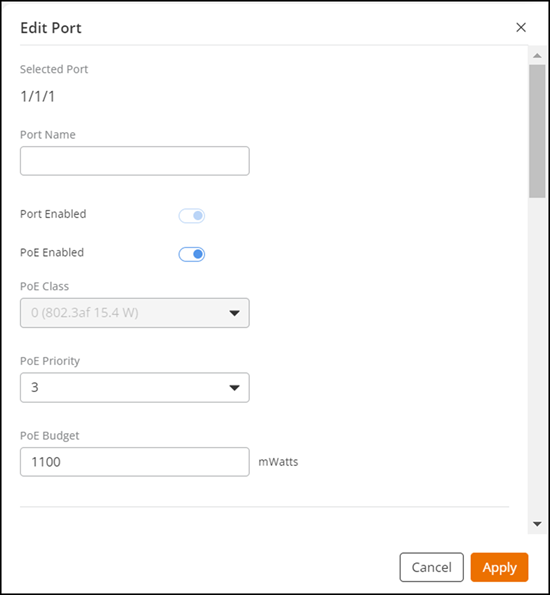
- Port Name: Change or modify the port name.
-
Port
Authentication: Toggle the switch on to enable this feature. When
enabled, use the drop-down menu to select the Authentication Profile for the
switch port. Click Customize to modify the profile settings. Refer to Understanding the Authentication Profile and Creating an Authentication Profile for more
information.
Note: The Port Authentication option must be disabled prior to enabling Port MAC Security or MAC ACLNote: When Port Authentication is enabled at the port level, the Auth Default VLAN cannot be changed at the switch level.
-
Profile: This feature is accessible only on a downlink
port; for an uplink port, this field is disabled and grayed out. Select an
existing ICX port profile from the drop-down list. To add a new ICX port
profile, refer to Adding and Managing an ICX Port Profile.
The Port Profile drop-down list displays the existing ICX port profiles (whether created from the RUCKUS One web interface or via the RUCKUS ICX console). If an ICX port profile is created and assigned from the RUCKUS One web interface, and the user manually changes the configuration on the RUCKUS ICX console, the ICX port profile name in the Port Profile drop-down list displays the suffix (Modified locally).
-
AV Profile: This
field appears only on ICX 8200‑AV models and only on downlink ports (uplink
ports show the control as disabled). Select an AV Profile to apply the
audio/video optimized baseline for that port (including QoS,
time‑synchronization, and multicast parameters). Refer to Adding an AV Profile for more
information.
If the AV Profile field is not visible, verify the switch is running the Router image.Note: Changing Port Speed or PoE after assigning an AV Profile can affect timing and traffic classification expected by AV endpoints. Assign the AV Profile first, then adjust speed/PoE only if required by the endpoint.
-
Port VLANs: Configuring VLANs on switch ports segments the
network, enhances security, reduces broadcast traffic, and improves performance.
You can edit tagged and untagged VLANs using one of the two options:
- Use Venue
Settings: Applies the VLAN configuration that is
inherited from the switch’s venue.Note: The Use Venue Settings option cannot be selected when the Port Authentication option is enabled.
- Edit:
Allows you to manually modify VLAN assignments for the selected port.
This includes choosing the untagged VLAN and adding or removing tagged
VLANs.
Depending on the option available, click Edit, and configure the following in the Select Port VLANs dialog. Or, if using venue setting, click Customize to open the same dialog.
- Untagged VLAN: Search by VLAN ID or name in the VLANs to activate on this port field.
- Select None, VLAN-ID-1 (Default VLAN), or any other available VLAN.
- Tagged VLANs: Search by VLAN ID or name in the VLANs to activate on this port field.
- Select the VLAN. You can click Select All to select all available VLANs by selecting the checkbox for faster selection and uncheck the checkbox to deselect the selected VLANs.
- Set as Voice VLAN: This appears when a VLAN is selected. Toggle the switch on to enable this feature.
- (Optional) Click Add VLAN to add a new VLAN.
-
Click OK.
Note: Select All applies only to the VLANs currently visible in the web interface. VLANs added after using this option are not automatically selected.Note: The ability to select a specific range of VLANs is not supported.
- Use Venue
Settings: Applies the VLAN configuration that is
inherited from the switch’s venue.
-
Port Enabled: Toggle the switch on or off to
enable or disable this feature. The port is enabled by default.
When enabled, the switch port is active and can transmit and receive data. This allows devices connected to the port to communicate with the network. Disabling a port prevents any data transmission through that port.
-
PoE Enabled: Toggle the switch on or off to
enable or disable this feature. PoE is enabled by default on PoE-capable ports
and for a non-PoE port, this feature is disabled and grayed out.
Activating Power over Ethernet (PoE) allows the switch port to supply power to devices such as IP phones, wireless access points, and cameras over the Ethernet cable.
-
PoE
Schedule: Configuring a PoE schedule on a switch port allows
automatic control of PoE-capable Ethernet ports based on a predefined weekly
schedule. You can specify when PoE must be enabled or disabled for each port
individually. Refer to Configuring a Custom PoE Schedule for a Switch Port for more information.
Note: Manually enabling or disabling PoE does not override the configured schedule. The PoE schedule automatically takes effect again at the beginning of the next hourly time slot.
To understand how PoE schedules affect port behavior, refer to Understanding Custom PoE Scheduling on ICX Switch Ports.
-
PoE power
by Class: PoE classes define the amount of power a connected
PoE-enabled device can receive from a switch.
Note: On ICX 8100-AV and ICX 8200‑AV models, available PoE classes depend on the model and the specific port range. If a class is not listed for the selected port, that class is not supported on that port.Select a value from the drop-down menu:
- Negotiate (Default): Powered Devices (PDs) that comply with the IEEE standard negotiate their classification with the Power Sourcing Equipment (PSE), which then provisions the corresponding class power. The system provisions non-standard legacy PDs with 15.4 watts of power. PDs can also negotiate their power requirements further through Link Layer Discovery Protocol (LLDP) power negotiations.
- Class 1 (Low Power): This class provisions up to 4 watts of power and is suitable for low-power devices such as certain sensors.
- Class 2 (Medium Power): This class provisions up to 7 watts of power, which is used for devices like basic IP phones.
- Class 3 (Full Power): This class provisions up to 15.4 watts of power for more demanding devices such as advanced IP phones and some wireless access points.
- Class 4 (High Power, PoE+): This class provisions up to 30 watts of power for high-power devices such as cameras and more advanced wireless access points.
- PoE Priority: PoE priority determines the order in which devices receive power from a PoE switch when the power budget is exceeded. Select a number from the drop-down menu.
- PoE Budget: A PoE budget is the total power a PoE switch can supply to all connected devices. It ensures the switch can power all devices without exceeding its capacity. It is measured in mWatts.
- Protected Port: A protected port prevents traffic from being forwarded to other protected ports on the same switch, enhancing network security. You can enable or disable this feature using the toggle.
- LLDP Enabled: When LLDP is enabled on a switch port, it allows the port to share and receive information about connected devices, aiding in network discovery and management. You can enable or disable this feature using the toggle.
-
Port
Speed: Port speed on a switch determines the rate at which data
can be transmitted through the network port. Select a port speed from the
drop-down menu. The list of port speeds is dependent on the Ethernet speed
rating of the port (such as 2.5G, 10G, 25G, and so on).
Note: Available speeds depend on the model and the selected port range (for example, 1/1/x access ports vs 1/2/x uplinks). Some ICX 8100-AV and ICX 8200‑AV models expose 2.5G/5G/10G on specific access ports, while other access ports remain 1G. If a speed is not listed for the selected port, that speed is not supported on that port.These values refer to the speed and duplex settings of a network port:
- None: The port does not use any specific speed setting.
- Auto: The switch and the connected device automatically choose the best speed for the port.
- 10-FULL: This setting indicates a port speed of 10 Mbps with full duplex, allowing simultaneous data transmission and reception.
- 10-HALF: This setting indicates a port speed of 10 Mbps with half duplex, permitting either data transmission or reception at one time, but not both.
- 25G-FULL: This setting indicates a port speed of 25 Gbps with full duplex, allowing simultaneous data transmission and reception.
- 100-FULL: This setting indicates a port speed of 100 Mbps with full duplex, enabling simultaneous data transmission and reception.
- 100-HALF: This setting indicates a port speed of 100 Mbps with half duplex, allowing either data transmission or reception at one time, but not both.
- 1000-FULL: This setting indicates a port speed of 1000 Mbps (1 Gbps) with full duplex, facilitating simultaneous data transmission and reception at 1 Gbps.
- 1000-FULL-MASTER: This setting is similar to 1000-FULL but designates the port as the master in a master-slave configuration used when one device controls the timing of data transmission.
Note:- Beginning with RUCKUS FastIron 10.0.20b and 10.0.10f, the RUCKUS ICX 7850-48C switch supports 2.5-Gbps and 5-Gbps port speeds for port numbers 1 through 48.
- When editing multiple port speeds, only the speeds supported by all selected ports will be available. For example, if port 1/2/1 supports 40G-Full, 100G-Full, and 10G SFP+, and port 1/3/1 supports 1000-Full, 10G-Full, 25G-Full, and 10G SFP+, the common available speed will be 10G SFP+.
- RSTP Admin Edge Port: An RSTP Admin Edge Port is a port set up to connect directly to devices like computers or printers. It skips the usual checks and starts forwarding data right away, helping the network work faster. You can enable or disable this feature using the toggle.
-
Point-to-Point MAC: Enables or disables direct
communication between two devices without any intermediary.
- Auto (default): Automatically assesses the duplex mode to decide the point-to-point link status.
- Enable: Declares the port to be on a point-to-point link for all VLANs.
- Disable: Declares the port to be on a non-point-to-point link for all VLANs.
-
STP BPDU
Guard: When enabled, this option shuts down a port if it receives
a Bridge Protocol Data Unit (BPDU) message, preventing network loops. You can
enable or disable this feature using the toggle.
Note: Beginning with RUCKUS FastIron 10.0.20b and 10.0.10g, if you enable STP BPDU Guard at the port level, the system will automatically enable BPDU Guard in the Error Disable Recovery settings at the switch level.
- STP Root Guard: STP Root Guard prevents a switch port from becoming a root port if it receives superior BPDUs, ensuring the designated root bridge remains the root. You can enable or disable this feature using the toggle.
- DHCP Snooping Trust: A DHCP Snooping Trust port allows DHCP server responses to pass through, blocking rogue servers and ensuring only trusted ports can send DHCP messages and acknowledgments. You can enable or disable this feature using the toggle.
- IPSG: IP Source Guard (IPSG) prevents IP spoofing by filtering traffic based on DHCP snooping or static IP bindings, allowing only authorized IP addresses. You can enable or disable this feature using the toggle.
- LLDP QoS: LLDP QoS uses LLDP to advertise and negotiate QoS parameters between devices, ensuring correct traffic prioritization across the network. You can click Create to add LLDP QoS configurations to the port, including the Application Type, QoS VLAN Type, VLAN ID, Priority, and DSCP.
-
Port MAC Security: When enabled, this option allows the
switch to automatically learn and bind MAC addresses to the port, ensuring that
only packets from authorized devices are allowed and preventing unauthorized
devices from accessing the network. Toggle the option to enable port MAC
security and for Sticky MAC List Size Limit, enter a
number ranging from 1 (default) through 8256. The value specifies the maximum
number of learned MAC addresses allowed to be added to the allow list.
Note:
- Ensure that port-level Authentication is disabled prior to enabling Port MAC Security.
- Reducing the Sticky MAC List Size Limit value results in the system deleting the existing Sticky MAC ACL and re-learning the MAC addresses. You will be prompted to confirm this action.
- Ingress ACL: An Ingress ACL (IPv4) on a switch port filters incoming traffic based on criteria like IP addresses, protocols, or port numbers to enhance security. Select the criteria from the drop-down menu. You can click Add ACL to create and apply a configuration profile to the switch's venue to add or edit the Access Control List (ACL).
- Egress ACL: An Egress ACL (IPv4) on a switch port filters outgoing traffic based on criteria like IP addresses, protocols, or port numbers to enhance security. Select the criteria from the drop-down menu. You can click Add ACL to create and apply a configuration profile to the switch's venue to add or edit the Access Control List (ACL).
-
MAC ACL: A MAC ACL on a switch port filters traffic based
on MAC address to enhance security. Select an existing MAC ACL policy from the
drop-down menu or click Add MAC ACL to
create and apply a new MAC ACL policy to the switch port.
Note: Make sure to disable 802.1x, MAC-AUTH, or 802.1x and MAC-AUTH authentication before attempting to configure the MAC ACL on a switch port.
- Tags: Tags are used to manage and organize network traffic. Enter a tag value.
- Cycle PoE: Click this button to power off and power back on again a PoE-enabled port to reset or troubleshoot connected devices.
- Click Apply to save the configuration. For an uplink port, the Modify Uplink Port dialog box is displayed and prompts you to apply changes.
- Click Apply Changes.