Adding and Managing an ICX Port Profile
You can implement ICX port profiles to dynamically configure ICX port settings based on the device connected, minimizing manual configuration efforts.
-
Select
Switch.
The Switch tab defaults to the Profiles sub-tab view, displaying a list of all configured ICX port profiles. Also accessible are the MAC OUI and LLDP TLV sub-tabs, where you configure match criteria for use in your ICX port profiles. Regardless of the sub-tab you are viewing, the Add ICX Port Profile button is always available in the top-right corner of the page.
Port Profiles - Switch Tab 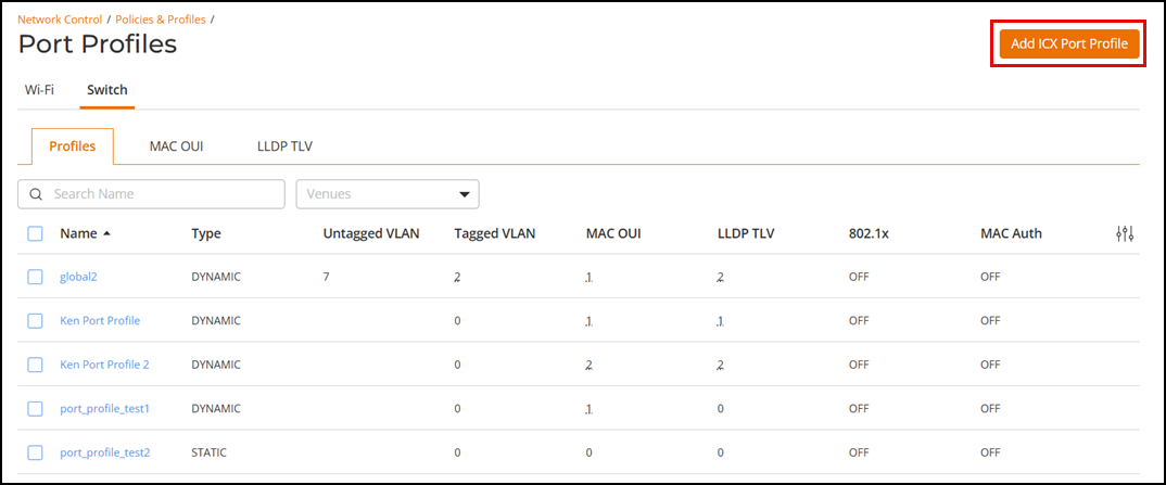
-
Click Add ICX Port
Profile to add a new ICX port profile.
Adding an ICX Port Profile 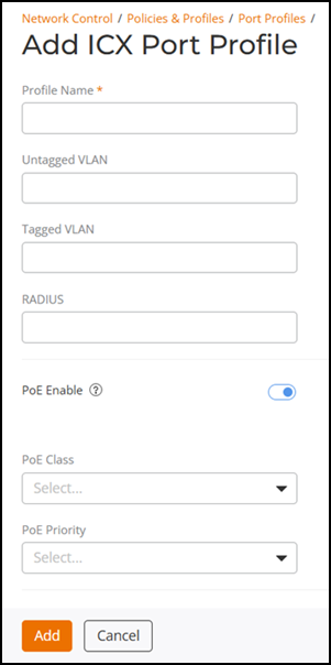
The Add ICX Port Profile page is displayed. Enter a profile name and configure the optional settings:
- Profile Name: Enter a unique name to identify the ICX port profile (up to 30 characters).
- Untagged VLAN: Enter a the VLAN into which untagged ingress packets are placed upon arrival. Valid numbers are 1 (default) through 4095, except 4087, 4090, 4091, 4092, and 4094.
- Tagged VLAN: Enter the VLAN IDs that you want to use to tag WLAN traffic that will use this profile. You can enter a single VLAN ID or a VLAN ID range (or a combination of both). The valid VLAN ID range is from 1 through 4094.
- RADIUS: Enter a valid IP address of a RADIUS AAA server.
- PoE
Enable: By default, PoE is enabled for the port.Note: PoE must be enabled in order to assign LLDP TLV and MAC OUI to this ICX port profile.
- PoE
Class: PoE classes define the amount of power a connected
PoE-enabled device can receive from a switch. Select a value from the
drop-down menu.
- Class 0 (Default): This class provides up to 15.4 watts of power. It is the default classification for devices that do not specify a power class.
- Class 1 (Low Power): This class supplies up to 4 watts of power and is suitable for low-power devices such as certain sensors.
- Class 2 (Medium Power): This class delivers up to 7 watts of power which is used for devices like basic IP phones.
- Class 3 (Full Power): This class offers up to 15.4 watts of power for more demanding devices such as advanced IP phones and some wireless access points.
- Class 4 (High Power, PoE+): This class provides up to 30 watts of power for high-power devices such as cameras and more advanced wireless access points.
- Class 5 (High Power, PoE+): This class provides up to 45 watts of power for high-power devices such as cameras and more advanced wireless access points.
- Class 6 (High Power, PoE+): This class provides up to 60 watts of power for high-power devices such as cameras and more advanced wireless access points.
- Class 7 (High Power, PoE+): This class provides up to 75 watts of power for high-power devices such as high-definition cameras, advanced wireless access points, and other power-intensive devices.
- Class 8 (High Power, PoE+): This class provides up to 90 watts of power for high-power devices such as high-definition cameras, advanced wireless access points, and other power-intensive devices.
- PoE Priority: PoE priority determines the order in which connected devices receive power from a PoE switch when the power budget is exceeded. A port with a higher PoE priority provides power to its connected device before a port with a lower PoE priority. Select a number from the drop-down menu. Add the following (values are based on testing in the GUI, meanings are based on FastIron documentation): Values are 1, 2, or 3, with 1 being highest priority and 3 being the lowest priority.
- Protected Port: A protected port prevents traffic from being forwarded to other protected ports on the same switch, enhancing network security. You can enable or disable this feature using the toggle.
- LLDP Enabled: When LLDP is enabled on a switch port, it allows the port to share and receive information about connected devices, aiding in network discovery and management. You can enable or disable this feature using the toggle.
- Port
Speed: Port speed on a switch determines the rate at
which data can be transmitted through the network port. Select a port
speed from the drop-down menu. The list of port speeds is dependent on
the Ethernet speed rating of the port (such as 2.5G, 10G, 25G, and so
on).
These values refer to the speed and duplex settings of a network port:
- 10-FULL: This setting indicates a port speed of 10 Mbps with full duplex, allowing simultaneous data transmission and reception.
- 10-HALF: This setting indicates a port speed of 10 Mbps with half duplex, permitting either data transmission or reception at one time, but not both.
- 100-FULL: This setting indicates a port speed of 100 Mbps with full duplex, enabling simultaneous data transmission and reception.
- 100-HALF: This setting indicates a port speed of 100 Mbps with half duplex, allowing either data transmission or reception at one time, but not both.
- 1000-FULL: This setting indicates a port speed of 1000 Mbps (1 Gbps) with full duplex, facilitating simultaneous data transmission and reception at 1 Gbps.
- 1000-FULL-MASTER: This setting is similar to 1000-FULL but designates the port as the master in a master-slave configuration used when one device controls the timing of data transmission.
Note: Beginning with RUCKUS FastIron releases 10.0.20b and 10.0.10f, the RUCKUS ICX 7850-48C switch supports 2.5-Gbps and 5-Gbps port speeds for port numbers 1 through 48. - RSTP Admin Edge Port: An RSTP Admin Edge Port is a port set up to connect directly to devices like computers or printers. It skips the usual checks and starts forwarding data right away, helping the network work faster. You can enable or disable this feature using the toggle.
- STP BPDU Guard: When enabled, this option turns off a port if it gets a Bridge Protocol Data Unit (BPDU) message preventing network loops. You can enable or disable this feature using the toggle.
- STP Root Guard: STP Root Guard prevents a switch port from becoming a root port if it receives superior BPDUs, ensuring the designated root bridge remains the root. You can enable or disable this feature using the toggle.
- DHCP Snooping Trust: A DHCP Snooping Trust port allows DHCP server responses to pass through, blocking rogue servers and ensuring only trusted ports can send DHCP messages and acknowledgments. You can enable or disable this feature using the toggle.
- IPSG: IP Source Guard (IPSG) prevents IP spoofing by
filtering traffic based on DHCP snooping or static IP bindings, allowing
only authorized IP addresses. You can enable or disable this feature
using the toggle.Note: IPSG must be disabled in order to enable Ingress ACL, 802.1x, and MAC Auth in this profile.
- Ingress ACL: An Ingress ACL (IPv4) on a switch port filters incoming traffic based on criteria like IP addresses, protocols, or port numbers to enhance security. Enter an IPv4 address.
- Egress ACL: An Egress ACL (IPv4) on a switch port filters outgoing traffic based on criteria like IP addresses, protocols, or port numbers to enhance security. Enter an IPv4 address.
- 802.1x: Toggle on to enable 802.1X authentication. This setting is disabled by default. This setting is automatically disabled if IPSG is enabled.
- MAC Auth: When enabled, the port first attempts to authenticate the attached device by MAC address, and if that fails, it attempts to authenticate the device using 802.1x. This option is disabled by default. This setting is automatically disabled if IPSG is enabled.
- Under Define Match
Criteria, select one or both of the following:
- MAC OUI: Click the MAC OUI drop-down list and select one or more of the MAC OUIs that you have already defined. To add a MAC OUI matching criteria entry, refer to Adding MAC OUI and LLDP TLV Matching Entries. For more information on IEEE OUI standards, refer to https://standards-oui.ieee.org.
- LLDP TLV: Select the LLDP TLV matching criteria from the LLDP TLV table. To add an LLDP TLV matching criteria entry, refer to Adding MAC OUI and LLDP TLV Matching Entries.
-
Click Add.
You can see the ICX port profile added in the Profiles table on the Profiles sub-tab. The profiles appearing here are at the tenant level (global level).
A notification is displayed on the Activities page accessible by clicking the
 icon at the upper-right corner of the RUCKUS One web
interface.
icon at the upper-right corner of the RUCKUS One web
interface.You can edit and delete an ICX port profile by selecting the checkbox for a specific ICX port profile and clicking Edit or Delete, respectively.
To search for a specific ICX port profile, enter the partial (at least two characters) or full port profile name in the Search field. All matching configuration profiles are displayed. You can filter the list of ICX port profiles by Venues. You can sort the list of ICX port profiles by profile name by clicking the associated column header.
Pause your pointer over the number in the Tagged VLAN, MAC OUI, LLDP TLV, Switches, and Venues columns to view more information. You can click the profile from the Profiles list to view its configuration details as shown in the following image.
ICX Port Profile Details 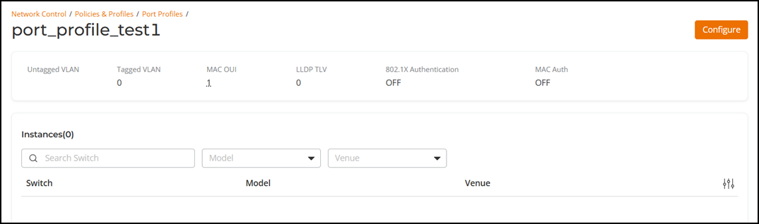
You can apply the ICX port profile at the switch level to individual ports by editing the port configuration (; refer to Editing a Switch Port for details).
At the switch level, you can view the list of associated ICX port profiles (whether created from the RUCKUS One web interface or the RUCKUS ICX console) from the Port Profiles sub-tab ( sub-tab; refer to Viewing the Port Profiles of a Switch for details).